
Last Updated on October 22, 2023 by Kevin Chen
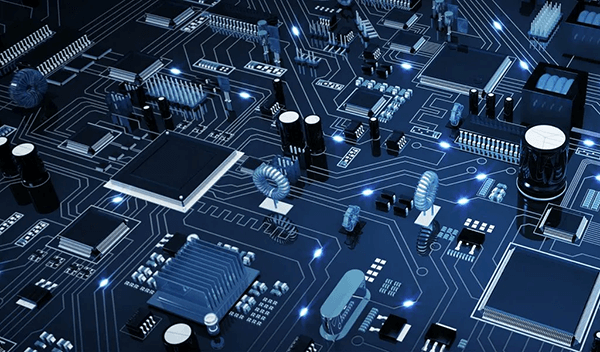
The Printed Circuit Board (PCB) is one of the essential concepts in electronics. Designers make them with conductive pads, tracts, and other notched components made of copper sheets which are glued on non-conductive substrates to ensure quality mechanical support and electronic components connections. Multi-layered, double-sided, and single-sided printed circuit boards are available. For example, active devices, resistors, and capacitors may be incorporated into the substrate of advanced PCBs.
PCBs are used in all electronic goods, even the simplest. PCBs are color-coded, which is one of the interesting facts about them. Red, purple, black, transparent, and white PCBs are most frequent, ranging from blue to green. Blue PCB boards, in contrast to other circuit boards on the market, have people asking what difference they make to the PCB board’s functionality.
While there is no evident difference between a blue PCB board and other hues, engineers and electrical designers are increasingly drawn to blue PCB electronics due to its appealing tint. Is it, however, just about the color?
This article covers everything you need to know about blue PCB boards, from their definition to their properties and the color blue’s connotation.
Let’s get started without further ado.
What do Blue Printed Circuit Boards Do?
Data or electrical circuits can be assembled into a working piece of hardware using blue PCBs. Through conductive routes, they provide required electrical and mechanical connections.
They’re blue because they look like a solder mask, not because their paint, dye, or mark is blue. The solder mask that shields the copper wires on the board is the same blue color as the solder mask. It looks like an Arduino blue board.
They’re well-known for more than simply their looks. The difference between planar traces and empty gaps is minor. In a blue solder mask, magnification is important because it aids in detecting manufacturing flaws. This is why designers favor blue circuit boards when building complex circuits and electrical devices like gaming PCs, RC robots, etc.
Blue PCBs have a variety of uses because of their appealing appearance:
- Mobile devices
- Appliances
- Digital clock and signage
- Musical instruments, synthesizers, and amplifiers
- Televisions and stereos
- Computers and printers
- RC drones, robots, and other vehicles
They are incredibly difficult to come by and are extremely rare. Because of this, they are the most expensive circuit boards available.
Power and signals can be sent between physical devices using a circuit board blue. Designers use solder to connect electronic components to the surface of the blue PCB.
Solder is a mechanical adhesive. It can also be noticed on the blue surface because it is metal. The components are soldered together to achieve a flawless fit. It enables designers to accurately remove any worn-out parts from the blue substrate without causing damage to the others in the event of repairs.
The Blue PCB’s Composition
Think of blue PCB as a cake tier. It’s made up of layers of various materials that alternate. The layers are laminated together with adhesive and heat to create a single item.
Layers include:
- A blue background (FR4)
- Copper
- Mask for soldering
- Silkscreen
Let’s look at the blue printed circuit board and see what each layer performs.
Substrate (FR4)
Let’s start with the foundation. Blue fiberglass serves as the substrate or base material. FR4 is another name for it. A printed circuit board’s substrate is the core that gives the board its thickness and rigidity. Flexible blue PBCs are also available, depending on the manufacturer. The majority of these are made of flexible high-temperature plastic. Blue PCBs come in various thicknesses depending on their use. Despite this, there are two conventional sizes: 1.6mm thickness and 0.8mm thickness. Custom blue printed circuit boards are also available from manufacturers. They can be customized for gaming PCs and remote control devices.
Some producers use epoxy resin or phenolics to create blue PCBs. They aren’t as strong or versatile as fiberglass PCBs. They are, however, significantly less expensive. An epoxy PCB may easily be identified from a fiberglass PCB. An epoxy blue PCB emits a distinct bad odor when soldered. They’re most commonly found in low-end consumer devices.
Before you buy anything, make sure you examine the substrate’s material. Low-cost substrates can put your entire circuit system at risk. The thermal breakdown temperature of phenolics and epoxy is low. When the soldering iron comes into touch with the board for too long, it causes them to smoke, delaminate, and burn.
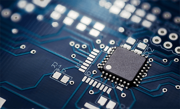
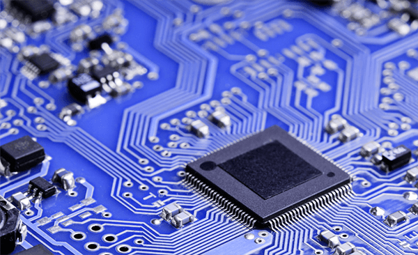
Copper
A thin copper foil is the second most significant component in blue PCB electronics. After the blue substrate, it is the second layer. Laminate these two layers using adhesive and heat. The copper layer is found on both sides of the substrate in double-sided blue PCBs. PCBs with copper on only one side are common in low-end devices. When we say 2-layer or double-sided blue boards, we refer to the number of copper layers on the board. The number of layers might range from one to sixteen. The layers might vary in number depending on the application and manufacturer.
Copper thickness can be specified by weight (ounces per square foot) and vary. One ounce of copper per square foot is found on several blue PCBs. However, certain customizable blue printed circuit boards may handle more power and use 2-3 ounce copper.
Solder Mask
The solder mask layer is the third layer on a printed circuit board.
It is visible on top of the copper foil. The solder mask is responsible for the color of traditional PCBs. Because the substrate for blue PCBs is blue, the solder mask can be either transparent or blue. Its purpose is to protect the copper layer from other metals, conductive bits, and solder. As a result, it is applied over the thin copper layer. It helps you solder to the right places while avoiding solder jumpers.
Silkscreen
In a blue PCB, the silkscreen is the final layer. It’s layered atop the solder mask layer. It aims to decorate the blue PCB board with symbols, numbers, and letters. The symbols and numbers are carved in a human-readable format, making assembly easier. These symbols serve as indications to aid in understanding the circuit board. Board manufacturers sometimes use silkscreen labels to indicate the functions of each LED or pin. A white silkscreen is typical. Designers favor black and white inks on blue PCBs, however. Nonetheless, numerous colors on a single PCB are uncommon.
Different Types of Blue PCB Electronic Boards
Now that you know how a blue PCB works let’s look at the many PCB varieties on the market, their properties, uses, and more.
Single Layer Blue PCB
Single-layer PCBs have a copper layer on one side of the blue substrate, as we discussed earlier. These boards benefit from power supplies, printers, SSDs, radio and stereo equipment, cameras, and calculators.
Double Layer Blue PCB
A copper layer is present on both sides of the blue substrate of a double-layer printed circuit board. Designers punch holes through the substrate to allow circuits to move from one side to the other. These boards can also be found in vending machines, industrial controllers, amplifiers, auto dashboards, instruments, LED lighting, HVAC systems, and power supplies.
Multi-Layer Blue PCB
Three or more double-layer blue PCBs make up a multi-layer PCB. The holes are drilled so that circuits can pass through them. A maximum of 50 layers can be found on the largest multi-layer boards. These circuit boards are used by medical gadgets, weather analysis machines, satellite systems, GPS technologies, data storage devices, and file servers.
Rigid
The strong base material of rigid PCBs prevents them from twisting. Designers make them strong to guarantee that they remain rigid throughout the device’s lifespan. They might have multiple, double, or single layers.
Flexible
Flexible PCBs can stretch and twist to fulfill the specialized requirements of electronic equipment.
Traditional Printed Circuit Boards vs Blue Printed Circuit Boards
As previously discussed, blueprinted circuit boards are identical to traditional circuit boards. Blue boards, on the other hand, are more attractive. The designer has etched the components into their surface, giving them a futuristic appearance. The contract between traces, planes, and vacant areas on blue circuit boards is shallower than on green and red circuit boards. In addition, to detect production flaws, the blue solder mask must be examined under magnification. Please keep in mind that the contrast between the silkscreen and the solder mask on blue boards is quite great.
Why Are Printed Circuit Boards Used?
PCBs provide a variety of advantages over traditional wired circuitry. They are appropriate for use in sophisticated systems because of their small size and low weight and their durability and ease of maintenance. Furthermore, their cheap production costs make them a very cost-effective solution.
These characteristics are some of the reasons PCBs are used in a variety of industries, including the following:
Medical
The introduction of PCBs has benefitted medical electronics substantially. From the electronic capability in PCBs, computers, imaging systems, MRI machines, and radiation equipment all continue to progress in technology.
Flexible and stiff flex PCBs are thinner and smaller, allowing for the production of increasingly compact and lightweight medical devices, including hearing aids, pacemakers, implanted devices, and highly tiny cameras for minimally invasive operations. Rigid-flex PCBs are a good choice for reducing the size of sophisticated medical equipment. They do away with the flex cables and connectors that occupy significant space in increasingly complex systems.
Aerospace
In the aerospace industry, rigid, flexible, and rigid-flex PCBs are commonly used for flight controls, flight management, instrument panels, dashboards, and safety systems. As aerospace technology progresses, the demand for smaller, more complicated PCBs in aircraft, satellites, drones, and other aerospace electronics has skyrocketed.
Due to the lack of connectors, flexible and rigid-flex circuits provide remarkable durability and mission survival. This allows them to work in high-vibration environments, while their tiny and lightweight design minimizes overall equipment weight and, as a result, fuel consumption. They are a very reliable solution for applications where reliability is critical.
Military
PCBs are utilized in military vehicles, ruggedized computers, sophisticated weaponry, and electronics systems routinely exposed to high impact, shock, and vibration (e.g., robotics, guidance, and targeting systems). More equipment integrates modern computerized technology as military technology evolves to suit increasing consumer demand, necessitating both the mechanical and electrical performance inherent in rigid-flex packaging and flex packaging. Thousands of pounds of g-force can be applied to these sorts of electronic packing without failure.
Last But Not Least
Most modern electrical gadgets start with printed circuit boards (PCBs). Whether single-layered or multilayered, printed circuit boards serve as the foundation for all other electronic components used in garage door openers, six-layer boards used in smartwatches, or 60 layers, very high-d Usedensity high-speed circuit boards used in supercomputers and servers.
Connections, resistors, Semiconductors, diodes, capacitors, radio devices, and capacitors are all installed on the PCB and communicate via it.
PCBs are appropriate for various applications because of their mechanical and electrical properties. Most PCBs created worldwide are rigid, accounting for nearly 90% of today’s PCBs. Some PCBs are flexible, allowing the circuitry to be stretched and folded into shape. They are occasionally utilized in applications where the flexible circuit must withstand hundreds of thousands of flex cycles without failing. Approximately 10% of the market is made up of flexible PCBs. Stiff flex circuits are a subset of these types of circuits. One section of the board is rigid – appropriate for mounting and connecting components – and one or more pour arts are flexible, offering the advantages of flexible circuits.
Printed electronics – often very simple, low-cost circuits that reduce electronic packaging costs to the point where electronic solutions can be designed to meet challenges never considered before – is a rapidly growing PCB technology distinct from those mentioned above. They’re frequently employed in electronics for wearable applications or disposable electronic gadgets, which opens up many possibilities for electrical designers.
Traditional printed circuit boards (PCBs) might be as simple as a single circuitry layer or as complex as fifty layers or more. They are composed of electrical components and connectors connected by conductive circuits – commonly copper –to route electrical signals and power within and between devices.
PCBs were invented in the early twentieth century, but technology has advanced rapidly. PCB technology has advanced while semiconductor packaging technology has advanced, allowing industry professionals to invest in smaller, more efficient electronics.
Conclusion
Professionals in various industries use printed circuit boards to improve the performance and manufacturing of their electronic systems. It is feasible to construct packaging for your electrical equipment optimized for its end application by carefully selecting materials and PCB fabricators.
Lastly, for more details on blue PCB or any other electrical component, contact us at ICRFQ. We manufacture the best electrical components in China.
If you want to find more Electronic Components Distributors, please check out the following articles:
Electronic Components Distributors In the USA
Electronic Components Distributors In UK
Electronic Components Distributors In China
Electronic Components Distributors In India
Electronic Components Distributors In Singapore
Electronic Components Distributors In Malaysia
Electronic Components Distributors In Vietnam
Electronic Components Distributors In South Korea
- Where to buy IC chips? The Best Guide? - March 26, 2024
- Breaking Down Barriers: Overcoming Obstacles in Cross-Border Electronic Component Trade - March 4, 2024
- Everything You Need to Know About Amplifier IC Chips - March 4, 2024


