
Last Updated on October 22, 2023 by Kevin Chen
If you’ve ever studied electronics, you may have heard the term “buck converter”. It sounds like something that only an electrical engineer could understand, but it’s actually quite simple to understand.
You see, a standard DC motor has a voltage range of around 3 volts up to 24 volts or more.
But that does not mean that any DC source outputs only those voltages. Many of them are much higher than that – like 48 volts for example. This is where a buck converter comes in handy.
Understanding how they work will help you choose the correct one for your project and save you from getting confused by their cryptic datasheets with lots of technical terminologies.
In this blog post , we’re going to show you everything you need to know about buck converters so that you can get started using them in your own projects right away.
What is a Buck Converter?
A buck converter is an electrical circuit that uses a diode and an inductor to reduce the voltage from a higher voltage DC source (i.e. 48V, 24V, 12V etc.) to a lower voltage DC output required by a load (like LEDs, motors, sensors, etc.).
It’s important to note that buck converters do not increase voltage. They only reduce the voltage from a higher voltage source to a lower voltage output.
A buck converter can be used for many different applications where you need a lower voltage DC output from a higher voltage DC source. This could be for driving low-voltage DC motors, powering sensors, or even charging batteries from higher voltage sources (more on this later).
How Does a Buck Converter Work?
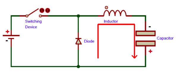
If you look at a buck converter circuit, you’ll notice that it has a diode and an inductor. It also has a control circuit that produces a pulsed control signal to the diode when the inductor is charged up.
When the power is applied to the buck converter, the diode starts conducting current, but the inductor blocks it from flowing into the load. Instead, it flows into the diode and charges up the inductor.
Once the inductor is charged up, the control circuit stops conducting current through the diode, and the inductor supplies current to the load. This process repeats as long as the circuit is powered.
Buck Converter Design
A buck converter is a current-source converter, meaning that the output current is always equal to the input current. This is why they are used in applications where you need a constant current.
The design of a buck converter depends on the voltage across the input and the voltage across the output. The voltage across the input of the circuit is the voltage supplied by the higher voltage DC source.
The voltage across the output of the circuit is the voltage required by the load. The voltage difference between these two voltages determines the design of the buck converter circuit.
Here are the steps to follow when designing a buck converter:
Step 1:Determine the input voltage and output voltage and also the current
The very first step is to know the exact values that you will be dealing with. This is because the values will be used in the design of the buck converter circuit. You need to know the input voltage and output voltage, as well as the current required by the load.
The Duty cycle of any buck converter is given by:
DC=Vout/Vin
Step 2: Determine the output power
The output power is the product of the input voltage, output voltage and output current. This is given by:
Pout=Vin×Vout×Iout
Step 3: Determine the minimum inductor value
The minimum inductor value will be determined by the duty cycle. The duty cycle limits the amount of current that can flow through the inductor at any time. This means that there will be times when there is a maximum current through the inductor and also times when there is no current flowing in it. The maximum amount of current that can flow through an inductor at any given time is called its saturation current and this is given by:
Isat=0.5×ln(1+DC)
This means that the maximum current through the inductor is equal to half of the saturation current at any given time. This can be used to determine the minimum inductor value and this is given by:
Lmin=Vin/Isat
Step 4: Determine the output capacitor value
The maximum current through the output capacitor is equal to the saturation current in the inductor. This means that any additional load current will cause the current in the inductor to drop and this will cause a reduction in voltage across it.
This means that there will be an increase in voltage across the output capacitor so it must be large enough to handle this increase. The maximum amount of voltage that can be applied across an output capacitor is called its ripple voltage and this is given by:
VRIPPLE=Isat×Vout/2
Parts and Components of a Buck Converter
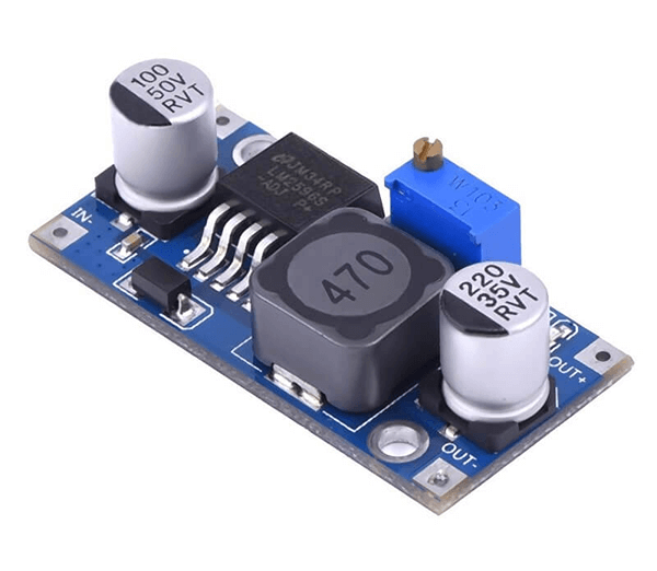
While there are many different types of buck converters, they all have the same basic circuit design. The basic components are an inductor, a diode, and a current regulating circuit like a transistor.
The inductor is basically a coil of wire that when supplied with current, stores that current in a magnetic field.
The diode is a device that allows current to flow in one direction but not the other. The current regulating circuit is used to control the amount of current flowing through the diode and inductor.
Other key parts include:
MOSFET: A MOSFET is a transistor with a metal oxide semiconductor field effect. It is a voltage-controlled device and the voltage applied to it is used to control the current flowing through it. MOSFET’s are used in many different applications but in a buck converter they are used as the current regulating circuit.
Diodes: Diodes are devices that allow current to flow in one direction but not the other. They are used as components of a bridge rectifier, which converts AC power into DC power. The voltage drop across a diode is used to regulate the amount of current flowing through the inductor and this keeps it from getting too hot and melting down.
-Capacitors: Capacitors store electrical charge when they are connected between two points by applying an external voltage across them. In buck converters, they are placed across the output to ensure that there is enough energy stored in them so that any sudden increases in load don’t cause problems with ripples on the output voltage.
-Inductor: The inductor is used in most DC-to-DC converters as it is a component that can store energy and release it when needed. It works by converting the current instantly from AC to DC and back to AC again and this is what makes the current flow through it vary with time. This is how the inductor acts as an energy storage component in the buck converter.
-Resistors: Resistors are components that restrict current flow by producing heat when they are connected across a voltage source. They are used to regulate current flow in a buck converter to ensure that there isn’t too much power flowing through the circuit and damaging any of its components.
What is Different about Buck Converters?
Buck converters are different from boost converters in that they reduce voltage. Boost converters increase voltage. For example, many modern cars use DC voltage to power their headlights and accessories.
They also use 48V DC batteries to power the car starter. While 48V is a great voltage for car accessories, it is too high for things like headlights. That is why many cars use buck converters to reduce voltage from 48V down to 12V to power the lights.
Buck converters are used in applications where you need a constant current, like to drive low-voltage DC motors, power sensors, or even charge batteries from higher voltage sources. Boost converters are used in applications where you need a constant voltage, like powering a microcontroller from a variable voltage source.
Efficiency of Buck Converters
The efficiency of a buck converter refers to the amount of power lost during the conversion process.
The efficiency can vary between 80% and 95%, depending on the design of the circuit. The efficiency of a buck converter is measured as the output power divided by the input power.
As mentioned earlier, the voltage across the input of the circuit is the voltage supplied by the higher voltage DC source.
The voltage across the output of the circuit is the voltage required by the load. The difference between these two voltages is the voltage drop across the circuit due to the resistance of the circuit components.
Advantages of Buck Converters
Some of the advantages of buck converters are;
-Provide constant current to the load:
-Ripple voltage is small:
-Provide high efficiency:
-High input voltage range:
Disadvantages of Buck Converters
The main disadvantage of buck converters is that they are not efficient. They lose a lot of power due to resistance in the components of the circuit. Therefore, they must be used when you need a constant current and not a constant voltage.
Types of Buck Converters
First off, it is important to know that there are two main types of buck converters – single-ended and dual-ended.
The single-ended buck converter has only one capacitance. The dual-ended buck converter has two capacitances – one input and one output.
The single-ended buck converter produces a single output voltage and the dual-ended buck converter produces two output voltages.
The output voltage of both the single-ended and dual-ended buck converters is lower than the input voltage.
How do I choose a buck converter?
Here are some technical parameters that you should look out for when it comes to buying buck converters:
-Maximum input voltage (Vin max): This is the maximum input voltage that the buck converter can accept.
-Minimum input voltage (Vin min): This is the minimum input voltage that the buck converter can accept.
-Maximum output current (Iout max): This is the maximum current that the buck converter can provide at a given input voltage.
-Maximum output power(Pout max): This is the maximum amount of power that a given output current can provide at a given input voltage.
-Power supply rejection ratio (PSRR) :This is how well a device rejects changes in input power source and supply ripple. The higher this figure, the better it works with noisy supplies.
-Operating frequency: This is the frequency at which the converter operates.
-Ripple and noise: This is the amount of noise that is present in the output voltage.
-Switching frequency: This is the number of cycles per second that the converter switches between high and low states.
-Efficiency: This is how much energy in put into a device as compared to how much comes out of it.
Applications of buck converters
The most common application for a buck converter are DC/DC converters, AC/AC converters, DC/AC inverters, DC power supplies, and battery chargers.
A buck converter can also be used for boost applications by simply connecting its input to its output. Since a buck converter works by decreasing an input voltage, it is sometimes referred to as a step-down converter or voltage reducer.
Buck converters are used in many different types of applications including power supplies (wall warts), battery chargers, motor controllers, LED lighting drivers, etc. When using a buck
Wrapping Up
It is clear that buck converters are an indispensable part of modern electronics and they will continue to be an important part of our lives for decades to come.
Hopefully, this article has helped you understand how buck converters work and how they can be used in your projects.
And in case you want to buy buck converters in China, let ICRFQ help you. We are a reputable sourcing agent for electronic components. You can trust us with your sourcing needs.
If you want to find more Electronic Components Distributors, please check out the following articles:
Electronic Components Distributors In the USA
Electronic Components Distributors In UK
Electronic Components Distributors In China
Electronic Components Distributors In India
Electronic Components Distributors In Singapore
Electronic Components Distributors In Malaysia
Electronic Components Distributors In Vietnam
Electronic Components Distributors In South Korea
- Where to buy IC chips? The Best Guide? - March 26, 2024
- Breaking Down Barriers: Overcoming Obstacles in Cross-Border Electronic Component Trade - March 4, 2024
- Everything You Need to Know About Amplifier IC Chips - March 4, 2024


