
Last Updated on October 22, 2023 by Kevin Chen
A busbar is a simple metallic strip that is usually used for the localized distribution of electrical energy. Busbars are usually housed in busway enclosures, panel boards, and switchgear.
The primary use of a busbar is to collect the electric energy from the supply feeders and transfer it to the outgoing feeders. For example, the busbar can collect power from one source station and transfer it to the next station or direct it to the user.
What is busbar protection scheme?
Busbar protection is a safety scheme or technique designed to prevent the damage or destruction of a busbar. It is also used to cut off the power supply to the busbar in case of an overload or short circuit.
A busbar protection scheme is a combination of various safety devices that are used together to protect a busbar
Classes of busbar protection schemes
Busbar protection schemes are classified into two types:
1) Localized Busbar Protection
2) Distributed Busbar Protection
Localized Busbar Protection Schemes
A localized busbar protection scheme is one in which each outgoing feeder has its own protective device. This type of scheme uses local overcurrent devices such as fuses, circuit breakers, and current limiting reactors.
The main advantage of this type of scheme is that it provides quick disconnection and fast fault-clearing ability for each feeder. However, this scheme is more expensive because it requires additional equipment such as fuses and circuit breakers at each outgoing feeder point. As a result, this type of scheme is usually used in industrial plants where there are many outgoing feeders from one point.
Distributed Busbar Protection Schemes
In most electrical installations, the number of outgoing feeders from one point (buspoint) is more than 20 and less than 100 per single buspoint (this varies depending on the installation).
For these installations, a distributed busbar protection scheme can be implemented without much cost increase since there will be only one fuse or circuit breaker per incoming line at the main distribution panel.
The busbar protection scheme is a cost-effective solution. The main advantage of this type of scheme is that it provides quick disconnection and fast fault clearing ability for each outgoing feeder.
How does a busbar protection scheme work?
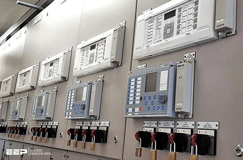
A busbar protection scheme works by incorporating several differential relays. These relays can either be a high impedance differential relay or it can be low impedance differential relay. both of these relay types are used for providing protection under their respective conditions.
So, how do these relays work?
The operation of such a relay can be described as follows:
The overcurrent condition on the outgoing feeder is detected by the surge protector. The overcurrent condition is then fed to the relay. Under these conditions, the relay will operate in the closed position and switch off all the outgoing feeds.
When a low impedance differential relay is used, it can be used on both high and low voltage feeds, as well as high and low current feeders. This type of relay works on lower current ratings than other relays.
The overcurrent condition on the outgoing feeder is detected by the surge protector. The overcurrent condition is then fed to the relay. Under these conditions, the relay will operate in the open position and switch off all the outgoing feeds.
When using both high and low impedance differential relays together, one should be used for high current and one for low current feeders. This ensures that both protectors operate separately when required while also ensuring the protection of each individual feeder.
Busbar Faults
As we have already mentioned, busbar protection schemes are designed to give protection against busbar faults. We can define a busbar fault s as a failure of the busbar.
Let us take a simple example.
In this case, we have a busbar fault where a short circuit occurs between two conductors. As a result, we get a short circuit in the busbar. Another example of a busbar fault is an open circuit. In this case, the current can flow through the busbar.
For protection against these kinds of faults, it is necessary to have some kind of means to protect against them, or else they may cause serious damage to our system and/or equipment.
Examples of busbar faults include:
-Mechanical damage due to external forces such as earthquakes and other vagaries of nature. Mechanical damage usually interfere with the connection of the busbar components. They end up rendering the busbar useless.
-Deterioration of the busbar material: this is usually the result of corrosion over time or during the installation of the busbar and the related components.
-Failure to make a connection between two conductors: this may be due to failure to properly connect the busbar components, or because they were improperly placed during installation.
-Faulty installation: it is possible that someone has used a faulty method of installing the busbar, causing it to fail and/or cause a fault in an electrical circuit. These faults are generally quite dangerous, as they can cause serious damage and/or injury to people and property if they aren’t properly dealt with before too long.
Methods used in busbar protection schemes
Different methods and techniques are used in providing fool-proof protection to the busbars. These methods include back-up protection scheme, current differential protection, and fault bus protection.
Let’s have a summary of what these methods are;
Current differential protection
This protection method is based on the principle that the current entering the busbar is equal to the current exiting the busbar. So, the current entering the busbar at the same time as the fault current is zero. In this case, there is no damage to the busbar and hence, it is not necessary to replace it.
This method is commonly used in phase-to-phase faults and also for ground faults.
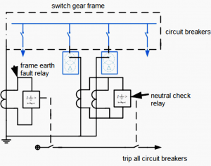
Fault Bus Protection
This busbar protection method is designed to shield the busbar structure and even the switchgear from the ground that connects to the circuit breakers. It provides a single connection point to the ground through a CT feeder which is connected to the overcurrent relay.
Take note that the primary function of the overcurrent relay is to control all the relays that trip the associating breakers connected to the busbar.
Back-up protection method
This is the simplest method used for protecting the busbar from faults. As expected, as the main power supply pipeline, we should expect the busbar to have some fault. To deal with this, a backup protection scheme is designed to supply power to the system.
While such a protection scheme method sounds viable, it also has some disadvantages. One of them is the low speeds of operation. It is not as fast and robust as the main relay pipeline. However, we cannot ignore the fact that it is economical and convenient to use.
Main zone and Check zone in busbar protection
Implementation of the busbar protection scheme will result in the disconnection of the feeders that were originally connected. To avert this, there will always a need to implement two zones: The main zone and the check zone.
The main zone is one that is connected to the main power supply pipeline and is used for supplying power to the system. The check zone is one that does not connect to the main power supply pipeline and is used for monitoring the faults in the main zone.
A sample of a busbar protection scheme
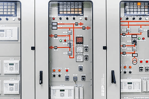
This is a very simple protection scheme. The busbar itself will be divided into two zones: The main zone and a check zone. Both of these are electrically isolated from each other by means of breakers or fuses.
The main zone will be connected to the electrical grid by means of a feeder breaker or fuse, while all other breakers/fuses are disconnected from this feeder breaker/fuse as well as they are disconnected from all other feeders/fuses as well.
The busbar itself will have two breakers/fuses which are connected in series with each other, one of them being used for controlling the overcurrent relay while the other one being used for controlling all other relays that trip on fault conditions.
In addition, there will always be one more fuse or breaker which can be used in case of emergency, making it possible to control any fault condition even if there is no overcurrent relay installed on this busbar terminal block.
This type of protection scheme can be operated at speeds up to 60 Hz (60-second cycles). It can also accommodate multiple buses per single circuit at different locations within a building structure or just within a single building structure if they are located on different circuits.
Key attributes of a busbar protection scheme
Typical busbar protection should have the following characteristics:
-It should be reliable: Since we are dealing with electricity, the issue f reliability will always come at the top of the list. The reliability of busbar protection can be defined as the probability of the system working under a fault condition.
Usually, reliability is measured in terms of time to trip (TTP), which is the time interval between the occurrence of a fault and the occurrence of a trip.
-The system should be robust: A busbar protection scheme should be able to withstand any short-circuit or overload condition that may occur in normal operation.
-It should be affordable: This requirement means that it must not require too much extra work for installation, maintenance and replacement. It should also not require an expensive expert to maintain it.
-It must be easy to install: The ease of installation will depend on how complex the installation process is, how many different buses are involved, etc.
-Should remain stable under all fault conditions: The system should not fail under any fault condition.
-It should be easy to maintain: The ease of maintenance will depend on how complex the maintenance process is and how many different buses are involved.
-Should not require an expert to maintain it: The process of maintaining a busbar protection scheme should be simple enough for any technician with basic knowledge in electrical engineering to perform.
-The system must be reliable: The busbar protection scheme must be reliable enough to withstand faults that may occur in normal operation, and it must remain stable under all fault conditions.
-It should be affordable: It should not require too much extra work for installation, maintenance and replacement. It should also not require an expensive expert to maintain it.
-It must be easy to install: The ease of installation will depend on how complex the installation process is, how many different buses are involved, etc.
Testing a Busbar protection
How do you test busbar protection?
The purpose of testing is to determine if the busbar protection scheme is functioning as intended. It will also help in determining how much current flows through each busbar, and how much voltage drops across each busbar.
To test, the circuit should be designed in such a way that it can be used to simulate a fault condition that may occur during normal operation of the protection scheme.
If there are several buses involved in the protection scheme, you must use several test points to test all of them at once.
By using a simulator and/or a circuit designed specifically for testing busbar protection schemes, you can simulate different fault conditions and measure their effect on the current flow through each busbar.
Not all faults are allowed for testing purposes; only certain types of faults are allowed to be simulated or measured by using a simulator or a circuit designed specifically for testing busbar protection schemes.
Conclusion
We have dissected everything you should know about busbar protection schemes.
The information provided in this article should be sufficient to allow you to understand the basic concepts involved in busbar protection.
If you are interested in buying busbar protection components, always seek expert advice. For instance, you can contact sourcing agents such as ICRFQ for further assistance.
If you want to find more Electronic Components Distributors, please check out the following articles:
Electronic Components Distributors In the USA
Electronic Components Distributors In UK
Electronic Components Distributors In China
Electronic Components Distributors In India
Electronic Components Distributors In Singapore
Electronic Components Distributors In Malaysia
Electronic Components Distributors In Vietnam
Electronic Components Distributors In South Korea
- Where to buy IC chips? The Best Guide? - March 26, 2024
- Breaking Down Barriers: Overcoming Obstacles in Cross-Border Electronic Component Trade - March 4, 2024
- Everything You Need to Know About Amplifier IC Chips - March 4, 2024


