
Last Updated on October 22, 2023 by Kevin Chen
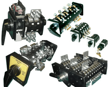
Cam switches are typically seen in low-voltage applications. The abrasion-resistant conductive material is used to make switching cams on a shaft. The cams open or shut the contacts when the shaft is rotated. Several cams are frequently positioned on a shaft, switching or switching multiple pairs of contacts simultaneously. We will look at what a CAM switch is and how it works in this article.
What is a CAM Switch?
Cam switches are electronic components used to switch alternating & direct current electrical circuits. They were used in switching power control circuits and operational control circuits for other electrical devices. Devices can be utilized in low-voltage circuits as well as circuits with voltages up to 500 V for alternating current & 220 V DC for direct current.
They are made of high-quality insulating and conductive materials. They are the product of successful experience in the development of current technology and knowledge gained through the creation of switching devices. Cam switches stand out for their small size, resistance to short-term circuit overload, and superior switching capabilities. To protect fuses against short-circuit current in an electrical circuit, utilize fuse links.
History of CAM Switch
Before 1900, Friedrich Natalis, who had worked for the Schuckert-Werke since 1897, had developed the cam-switching idea in Germany. However, Johann Sigmund Schuckert, the founder of the electrical engineering firm Schuckert & Co, offered cam switches with cam rollers and spring-loaded individual switches in 1895.
Over time, the word cam switch has been applied to such and related devices. Since 1901, Schuckert has also provided copper-carbon switching devices with spark-blowers for Natalis’ “carbon control switch”. Even when the rifle control pushed it to a more cost-effective location, the primary current CAM switch maintained some relevance. The cam switch did not debut in micromachine manufacturing until the early 1930s. In 1931, General Electric GE introduced the SBl, a 20A auxiliary current control switch that was essentially a mini version of the huge main control switches.
The devices included simple interruption and silver crossover, and a snap mechanism in some cases. Around 1940, the first cam switch, developed by Ghielmetti of Solothurn, Switzerland, started to replace traditional roller switches throughout Europe. Auxiliary current control switches with associated circuits could also be provided. They were sold under the Ghielmetti-Clavier brand name. Kraus & Naimer (from Vienna) manufactured the first company-owned cam switch, the C15 (15 A), in September 1948. The business also introduced the world’s first cam-designed cam switch in 1949. A similar design was followed by Kraus & Naimer cam switches C30 (30A) in the early 1950s.
The C16 to C200 Naimer & Kraus cam switches, which were introduced to the market in 1951, had a significant impact on the cam switch’s evolution and the roller switch’s debut. They had a 2-stage motor switching capacity and interruption proportional to the rated current. Cam switches were later developed as an industry-standard due to many possible combinations and considerable supplementary equipment as distinguishing features. The world’s smallest cam switch (type CA4N) was designed by Kraus & Naimer and has been on the market since 1994.
What is the design of a CAM Switch?
This gadget’s design is due to the usage of “cams” that activate a certain “pusher,” as the name suggests. The cam switch device necessitates a collection of switching elements, the position of which may be adjusted to reach a certain location for the functioning of various switching circuits. A switching program is the arrangement of contacts and cameras. They are contained within the melamine-based plastic casing.
Electric arcs & eddy currents do not affect such housing. The cam switch’s design allows all contacts to be turned on and off practically at the same time. The fact that one element’s cam is mechanically coupled to other elements ensures this. Silver in a contact device improves switching properties and increases fatigue rate since it can tolerate an electric arc better than identical copper.
A locking drive mechanism is needed because the switch must still be set in a specific position. A drive movement limitation is included in the design as well. Its goal is to set the switch to the far right. A square rod serves as the device’s drive or shaft. It must be built of metal to sustain the load when scrolling, ensuring dependable functioning and good contact switching. When motor control is employed, this is extremely significant. A handle composed of insulating material is utilized to control the drive of the switch.
Principle of Operation
The cam switch works on the concept of turning the apparatus drive to include a specified group of contacts. The drive spins around on its axis & operates the cams situated on it when the handle is rotated to the desired position. These, in turn, close down a certain set of contacts. The switching diagram generated based on the essential connection diagram can help you learn how the contact group operates.
When the motor is in the required location, a specific locking mechanism secures the switch, and the circuit begins to operate. It is essential to turn the handle again to get to the zero position. They are separated into switches with an automated return of the lever to the position and manual switches based on the concept of action.
Types of CAM Switches
Cam switches come in a variety of shapes and sizes.
Isolator switches
The isolator is a mechanical switch that is used to isolate a section of an electrical circuit when it is required. Isolator switches are used to open electrical circuits when there is no load. When the line is busy, it’s not a smart idea to open it. These are typically utilized on both ends of the circuit breaker, making circuit breaker repair quick and painless.
An electrical isolator is used to isolate any sort of electrical component from the system, whether it is online or offline. During detaching, the isolator lacks a method to prevent arching. An electrical isolator switch, similar to those used in electrical substations, Unless there is a little amount of load present, is typically used to disconnect a power transformer once it is in the no-load state. When the system is fully loaded, the isolators do not operate.
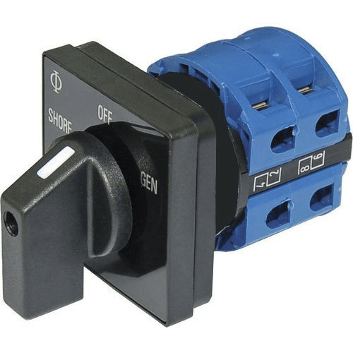
Changeover switches
When a power outage occurs, a changeover switch is used to transmit power to a local generator from the commercial power system. They connect directly to the commercial electricity source, generator, line, and dwelling and are called “transfer switches.” In the event of a power outage, a house or company owner can use a changeover switch to automatically switch to the generator.
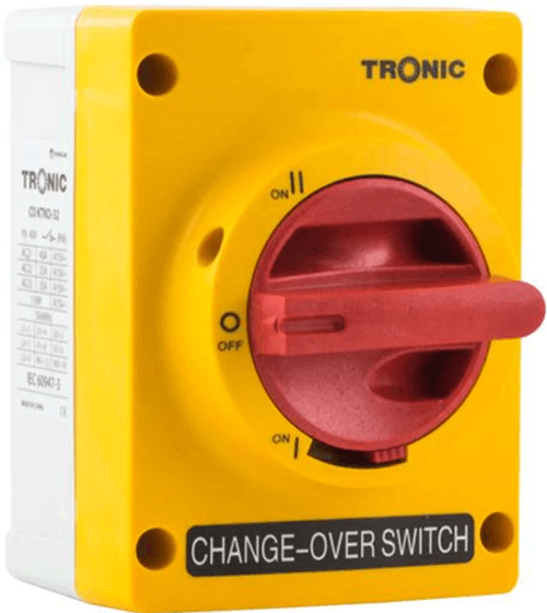
Despite the fact that there are dozens of distinct types of changeover switches, most of them fall into one of two categories: automatic or manual. During a power outage, an automatic changeover switch switches the electricity to the home, avoiding the need to switch manually. On the other hand, a manual changeover switch requires the homeowner to flip a switch to switch the power demand from the commercial grid to the generator.
Voltmeter Selector Switches
On a three-phase system, voltmeter selector switches must switch between phases for measurement. The voltmeter selector switch can be used to choose between line-line voltage or line-line and line-neutral voltage, whilst the ammeter selector switch can be used to switch between three-phase line currents. The switch’s output can then be sent into a piece of analog measuring equipment. The switches provide long-term reliability and high-current contacts. The switch facia measures around 48mm by 60mm and the switch terminals are finger proof. Each switch can be customized with a variety of interchangeable legend plates.
Gang Switch
Multiple light circuits can be controlled with gang switches from a single panel. They’re an essential piece of equipment in most business buildings, and they’re also useful in larger rooms with multiple lights for domestic clients.
Advantages of CAM Switch
The use of a cam switch provides some advantages.
- It’s incredibly easy to use.
- It functions similarly to a transfer switch, transferring energy from one location to another.
- It is inexpensive and small in size.
- It doesn’t require any upkeep.
- It has a high level of IP security.
- It can be installed within the enclosure or on the panel door.
- It includes a variety of different contact options.
- It can work in both cold and high temperatures without losing performance.
- It takes only a few minutes to set up.
- Electrically and mechanically, it lasts a long time.
Disadvantages of CAM Switch
There are some disadvantages to using a cam switch. The following are a few of them:
- It has no built-in protection against thermal and magnetic currents.
- It is not possible to control it remotely.
- To switch it, a physical rotating force must be exerted.
- It isn’t capable of switching very high currents.
Conclusion
A cam switch is an electrical component that can be very useful. It has a lot of benefits, which is why it’s so popular in many households and businesses. We hope you’ve found this article to be helpful.
Lastly, for more details on Cam switches or electrical components, contact us at ICRFQ. We manufacture the best electrical components in China.
If you want to find more Electronic Components Distributors, please check out the following articles:
Electronic Components Distributors In the USA
Electronic Components Distributors In UK
Electronic Components Distributors In China
Electronic Components Distributors In India
Electronic Components Distributors In Singapore
Electronic Components Distributors In Malaysia
Electronic Components Distributors In Vietnam
Electronic Components Distributors In South Korea
- Where to buy IC chips? The Best Guide? - March 26, 2024
- Breaking Down Barriers: Overcoming Obstacles in Cross-Border Electronic Component Trade - March 4, 2024
- Everything You Need to Know About Amplifier IC Chips - March 4, 2024


