
Last Updated on October 22, 2023 by Kevin Chen
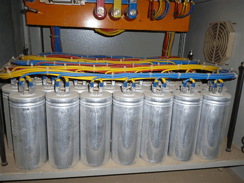
A capacitor bank is created when several capacitors are connected. Both series and parallel connections are possible. A capacitor bank has a wide range of benefits and uses. These are frequently employed for improving power factors and compensating reactive power. These can be organized at power plants or substations—the Farad unit of capacitance. Large residential communities, college campuses, and industrial facilities commonly use a lower-size capacitor bank to boost the power factor. It is imperative to increase the power factor since a low power factor at some point could affect the local power balance and result in fines from the electrical distribution companies.
What Is A Capacitor Bank, And How Does It Work?
A bank of capacitors is a collection of numerous identical capacitors connected in parallel or series. Phase shifts or power factor delays inherent in AC electrical power sources are two examples of undesired qualities that these groupings of capacitors are often employed to fix or counteract. Capacitor banks can also be used in DC power supplies to increase the amount of energy stored and improve the power supply’s ability to handle ripple currents.
Heavy industrial settings with working loads composed of electric transformers and motors are the typical locations where the employment of a capacitor bank to remedy AC power supply irregularities is found. Electric transformers and motors are inductive loads, which pose a challenge to the power supply because they result in phase shift or power factor lag, two conditions that are troublesome for this kind of working load. This unfavorable occurrence might result in significant reductions in the overall system efficiency and an increase in the power supply cost.
These phase shift problems are substantially eliminated or mitigated by including a capacitor bank in the power supply system, making the power supply far more effective and affordable. The installation of a capacitor bank is also one of the least expensive ways to address power lag issues, and maintaining a power factor capacitor bank is easy and affordable. One thing that should always be kept in mind while dealing with any capacitor bank or capacitor is the possibility that the stored energy, if improperly discharged, could result in severe burns or electric shocks. Care should always be used when handling any capacitor because improper handling or disposal can result in explosions.
Capacitor Bank Types
A capacitor unit is the standard name for a capacitor bank’s unit. Similar to the production of one-phase units, these units can be produced. A complete three-phase capacitor bank is created by connecting these units primarily in the shape of a star/delta connection. Currently, 1-phase capacitor units are the most widely produced, but 3-phase capacitor units are now less usually produced.
Internally Fused
There is a specific layout in which an internally fused can be designed. Various elements are connected in series and parallel, depending on their grade. An individual fuse unit can be used to safeguard each capacitor element separately. As the name suggests, the fuse units and capacitor elements are housed inside the same enclosure. Every capacitor element in this kind of bank is incredibly tiny and nonetheless meets ratings.
Therefore, there won’t be any impact on the bank’s operations if any of the capacitor’s components fail even if one or more damaged capacitor parts, a capacitor bank of this type can still function properly.
Internally fused types have a lot of benefits, including ease of installation and maintenance. An internally fused has the drawback that the entire bank must be replaced if multiple capacitor elements fail. Therefore, it is not possible to replace a single unit.
Externally Fused
Every capacitor unit has a separate externally provided fuse in an externally fused kind. The fuse unit will be harmed if any capacitor unit malfunctions. This bank will operate without interruption until the fuse unit separates the damaged capacitor unit.
For each phase of the bank, this type allows for the parallel connecting of capacitor units. If one component fails, the performance of the entire bank won’t be significantly impacted. When one capacitor unit is missing from a single-phase, that phase’s capacitance will be lower than the capacitance of the other two phases.
This will impact high voltage in the other two phases of the bank. Once the fuse unit explodes in this type, a visual inspection can be used to identify a defective unit. The usual capacitor unit rating spans the range of 50 KVAR to 40 KVAR. One of the primary requirements is this.
The fundamental drawback of this bank is that even when every unit in the bank is working correctly, an unbalance can be seen if one of the fuse units fails.
Fuse Less
A capacitor string can be created in an ineffective type by connecting many fuse units in series. A capacitor bank is created for each phase by joining these strings in parallel. Then, to create a complete three-phase bank, three comparable phase banks are joined using the star/delta connection.
The strings of capacitors are not shielded by a fusing mechanism, either internal or external. As a result, in this kind of system, even if one of the string units has a short circuit or other problem, the current flow through the entire string remains unaffected because numerous other capacitors are connected in series across this channel.
When the string unit’s internal short circuit effect is minimal, the capacitor bank can be built to delay replacing the defective unit. This is the primary reason why, when a unit becomes faulty, it is not required to immediately replace it with a new one from the bank’s system.
Capacitor Bank Connections
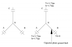
The capacitor bank can be connected in two different methods, star and delta, but the delta is more frequently utilized. As a result, it’s unclear which connection would be best for a bank. We will now discuss these two links, their advantages, and their disadvantages. As a 3-phase system uses a 3-phase capacitor bank for power factor correction, which may be coupled in a star or delta pattern, this is the primary application.
Capacitor Bank in Delta Connection
These banks are utilized for less than average voltage when they are utilized in a delta connection. The capacitor bank in a delta connection can be used for high voltage. Still, it is occasionally impossible because the whole phase voltage is delivered across every capacitor in a delta connection. In contrast, in a star-type connection, it is lower than the applied phase voltage across the capacitor. As a result, the following section discusses a wiring schematic for a three-phase capacitor bank employing two connections.
Therefore, the capacitor’s voltage rating must be high if we use a delta connection at high voltage. As a result, producing high voltage capacitors is often expensive and impractical.
Capacitor Bank in a Substation
As we’ve seen, this significantly impacts the power factor. These banks are put in substations for this use. To optimize the voltage profile, several capacitors are also linked in series. As observed in the power factor angle above, when this bank is installed, the capacitor current—also known as the charging current—always leads the voltage.
When a capacitor bank is added, the current overtakes the voltage, and the power factor angle decreases. Improvement in the power factor is implied by a reduction in the power factor angle. It also provides reactive power correction, which assumes a crucial role. The improvement in power factor also leads to reactive power compensation.
When inductive loads are installed on the load side, more reactive power is required. To produce the necessary magnetic flux, inductive loads require reactive power. Reactive power is more crucial in proportion to how inductive the load is. Inductive loads, therefore, use reactive power. Power factor decreases as reactive power are used up because the load becomes more lagging. Reactive power usage imbalances the way power is consumed, resulting in greater losses. By doing this, the plant would be under more stress.
This can be installed to assist with the system’s need for reactive power. The power balance is improved, and the losses subsequently decrease as reactive power is added. Furthermore, it aids in boosting the plant’s effectiveness.
Why is Capacitor Bank Testing Important?
Capacitor banks provide accurate power factor (pf) adjustment within the power system. As a result, depending on where it is installed, the pf correcting unit has varied operating parameters. Different elements such as time, moisture, temperature change, and harmonics will alter how capacitor bank power factor adjustment is calculated.
Capacitor banks that are already linked will become useless if they are not examined thoroughly within a certain time. The capacitor’s performance can deteriorate; power factor loss might occur if your power system’s power factor (pf) is reduced. An ANSI/IEEE or other standard is used throughout the testing. Three different kinds of tests are run, including type tests, design tests, regular testing, production tests, and pre-commissioning and field tests.
Conclusion
So far, we’ve looked at the capacitor bank’s function, setup, connections, and uses. Capacity banks are one of the most practical equipment needed in substations, residential buildings, and businesses. We leave it up to the reader to consider two intriguing elements of this. The first is where a capacitor bank should be placed. It refers to where the bank should be situated—at the plant’s start, middle, or end. Can we control the capacitor bank’s capacitance as the other factor? If so, what supplementary equipment should we use?
For more info on capacitor bank, contact us at ICRFQ. We manufacture the best electrical components in China.
If you want to find more Electronic Components Distributors, please check out the following articles:
Electronic Components Distributors In the USA
Electronic Components Distributors In UK
Electronic Components Distributors In China
Electronic Components Distributors In India
Electronic Components Distributors In Singapore
Electronic Components Distributors In Malaysia
Electronic Components Distributors In Vietnam
Electronic Components Distributors In South Korea
- Where to buy IC chips? The Best Guide? - March 26, 2024
- Breaking Down Barriers: Overcoming Obstacles in Cross-Border Electronic Component Trade - March 4, 2024
- Everything You Need to Know About Amplifier IC Chips - March 4, 2024


