
Last Updated on October 22, 2023 by Kevin Chen
The term “color code” or “color code system” refers to a method of displaying information using various colors. In a color-coding system that the UK has adopted, the color red denotes danger, and the color white denotes safety. Similarly, the color code is employed in other systems, including navigation, the military, electronics, video games, social interactions, and more. Neutral, Phase and ground wires are each represented by a specific color in the electronics industry’s color-coding system. Electronic color-coding primarily depicts different electronic components and their values, including capacitor, resistor, and inductor color coding.
What is a capacitor?
The most common electronic component, after resistors, is the capacitor. Every electronic circuit, including computers, televisions, and other devices, uses capacitors. Electronic equipment that holds an electrical charge is known as a capacitor. A primary capacitor comprises two conducting plates separated by a dielectric, an insulating material, or a medium.
Electric charges in opposition to one another build up on the capacitor’s two plates when voltage is supplied. Or, to put it another way, the capacitor begins to charge when voltage is introduced. Due to this, there is a potential disparity between the two plates.
The capacitor charges until the voltage between the plates, or potential difference, is lower than the external voltage. The capacitor finishes charging when the voltage or potential difference between two plates reaches the external voltage.
Capacitance is the term used to describe a capacitor’s capacity to store electric charge. A capacitor’s capacitance is expressed in farads. The area of the conducting plates and the space between them primarily determine the capacitance of the capacitor.
Big amounts of electric charge can be stored in capacitors with plates with a large surface area and a close spacing between them. On the other hand, capacitors consisting of large-separation-distance plates with limited surface areas will store minimal electrical charge.
What is the color code?
Generally speaking, “code” refers to the secret representation of information in various ways employing signals, symbols, and characters. Symbols or signals serve as codes in this situation. Similar to how we specify a capacitor’s capacitance (information) using different colors, so do we with capacitors. The capacitor’s coating’s many colors serve as codes in this instance. Other electronic parts, like resistors, inductors, and capacitors, employ color codes.
The term “electrical color code system” refers to identifying the values of electronic parts like capacitors, resistors, and inductors using the color codes written on them. Early in the 1920s, the radio makers organization, a component of the Electronic Industries Alliance, established this technology (EIA).
What Are Capacitor Color Codes
Electrical professionals can quickly identify and comprehend capacitors thanks to the color codes inscribed on their bodies. These color codes denote the capacitor’s tolerance, voltage, and capacitance values. The decimal point is difficult to see when a capacitance value is expressed as a decimal value. The actual capacitance value will be misunderstood as a result of this. Decimal points denote a number’s position and weight rather than letters like p (for pico) or n (for nano).
Consider a capacitor that is designated as n47 = 0.47nF, 4n7 = 4.7nF, or 47n = 47nF, for example. 100 × 1000pF or 100nF would be the value of a capacitor designated 100K. Capacitors are sometimes labeled with the capital letter K to indicate a value of one thousand picofarads. The worldwide color-coding system can lessen misunderstandings caused by labeled characters, numbers, and decimal points. It was created many years ago as an easy method of determining capacitor values and tolerances. The capacitor color code scheme is a color band that is organized spectrally.
Capacitor Color Code Examples
Ceramic Disc Capacitor
The dielectric material in this capacitor is ceramic (insulator). They use the names disc capacitor and multi-layer chip capacitor (MLCC). 1 nanofarad to 1000 microfarad is the range of values for ceramic disc capacitors. They are widely used in electrical circuits due to their lower
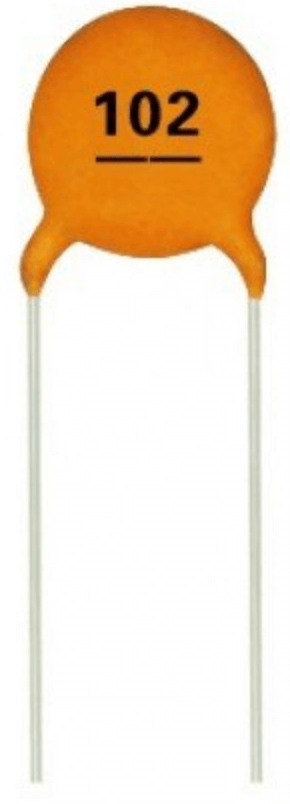
inductance, resistance, and enhanced frequency response. The ceramic or disc capacitor seen below has a three-digit number.
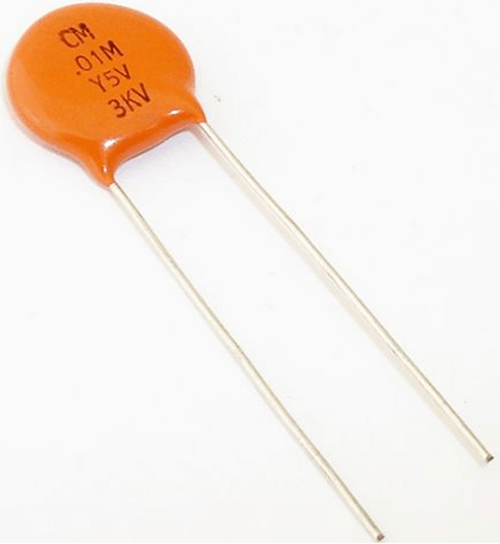
There is a three-digit code 103 printed on this. The third digit is a multiplier. To determine the capacitance value of the specific capacitor, we should multiply the first and second digits by a third digit. The example is as follows: 103k=10 x103, which is 10000pF, 10nF, or 0.01F.
Let’s look at one more example. This capacitor has the number 224 inscribed on it, which equals 22 x 104 or 220000pF (220nF) in terms of capacitance.
Aluminum Electrolytic Capacitor
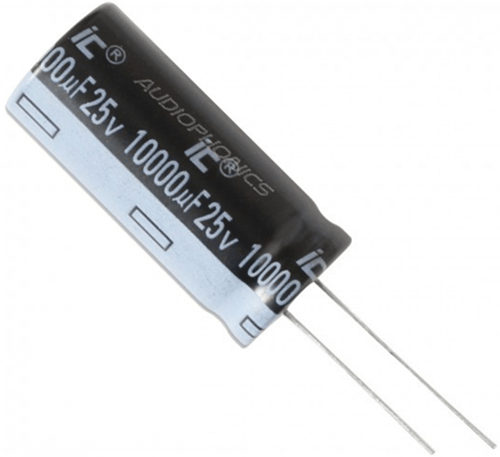
These aluminum-made electrolytic capacitors are used for power supplies and switching DC circuits. The capacitance value and voltage are listed on the body of this capacitor, along with the color code. Comparing this capacitor group to other groups of capacitors, it has low ESR values.
Surface Mount Ceramic Capacitor
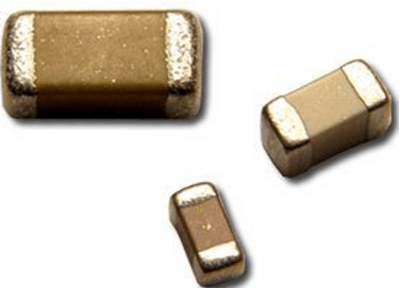
Capacitors of this type are ideal for users that require space and money savings. Picofarad to microfarad ranges is available for them. Various ceramics have different dielectric properties, affecting temperature and voltage ratings.
Color Coding of Capacitor
To comprehend the color code for capacitors, it is first necessary to be familiar with their many characteristics, including their value, tolerance, working voltage, and leakage current.
Capacitor markings often consist of four or more colors or dots. The first and second colors marked on a capacitor with four color bands indicate its value, and 3rd color band indicates the picofarads decimal multiplier. Additional fourth or colored bands thereon stand for different things for different kinds of capacitors.
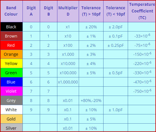
The value is shown on the capacitor either directly or using a color-coded capacitor. The working voltage of the capacitor is the highest voltage it can withstand before experiencing a dielectric breakdown, and the table below shows the color-coded representation of this value. Practically speaking, each capacitor will have some leakage current, which in perfect capacitors is zero.
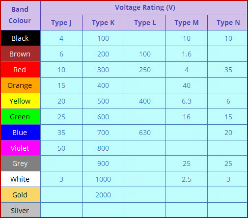
In the case of a capacitor with five bands, the first band corresponds to the first number in the capacitor color coding table given in the above illustration. The second band symbolizes the following number from the chart, and the third band symbolizes the quantity of zeros. The fourth band shows the tolerance value, which is typically denoted by the colors black (20%), white (10%), and green (5%). The fifth band shows the capacitor’s operating voltage (250V-red and 400V-yellow).
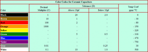
The above illustration illustrates the color code for ceramic capacitors, where the first column shows several color types and the second column shows the value each color denotes. The capacitor’s tolerance value is shown in the third column (with sub-columns for values above and below 10pf), and the temperature coefficient is shown in the fourth column. Indicating the value in picofarads or microfarads on ceramic capacitor labels is customary. This depends on whether the amount is one or more. A few capacitor color coding representations use ‘R’ as a decimal, so instead of ‘4.7’, ‘4R7’ is used.
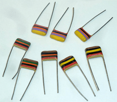
I hope this essay provided some fundamental knowledge about capacitor color coding. Let’s talk about a few instances to learn how to determine a capacitor’s value using its color code. Think about a metalized polyester capacitor, which has five bands and is depicted in the figure below.
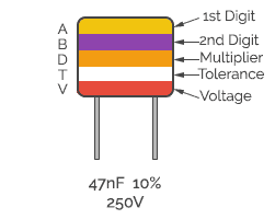
Using the capacitor color code chart explained above, it is possible to calculate the value of the five-band capacitor depicted in the above picture. With a tolerance value of 10% and a working voltage of 250V, it is discovered that the five-band capacitor has a capacitance value of 47nF. You may calculate the capacitance tolerance value using the table of letter codes below.
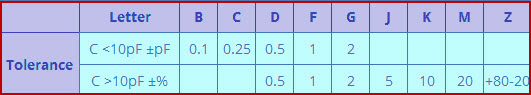
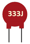
Think of a different capacitor where the value is represented as in the figure below. As a result, the capacitor value can be calculated as follows: J stands for the tolerance value of the capacitor, and the first three digits are 3, 3, and 3. The third digit, “3,” is a multiplier in picofarads. As a result, the capacitor’s value is 33pF multiplied by 1000 (the multiplier is 3 = three zeros), which is 33nF or 0.033uF.
The capacitor’s value, whether in Picofarads, Nanofarads, or Microfarads, can be readily determined using the codes in the table below.
Disc & Ceramic Capacitor
The Capacitor Color Code scheme has been in use for a long time on unpolarized mica and
polyester molded capacitors. There are still a lot of “vintage” capacitors around, even though this color-coding technique is no longer effective. The BS1852 Standard and its successor, BS EN 60062, which replaced the colors with a letter or number coding system, are the current standards for tiny capacitors like film or disk kinds.
In most cases, the code comprises two or three digits plus an optional letter code to indicate the tolerance. The value of the capacitor alone is provided in picofarads when a two-number code is used; for instance, 47 = 47 pF and 100 = 100 pF, etc. The two value digits plus a multiplier make up a three-letter code, just like the color codes for resistors in the resistors section.
Using the number 471 as an example, 47*10 Equals 470pF. The following tolerance letter code is frequently used in conjunction with three-digit codes.
Conclusion
Tens of capacitors (made of tantalum, ceramic, film, aluminum, etc.) are available for commercial-grade, high-voltage, high-temperature applications in RF and microwave technology as well as power-efficient applications in the aerospace and defense industries. Each capacitor is identified by a color code and a unique set of technical requirements. To suit your needs for an electronic application, you must pick the appropriate one.
For more details on capacitor colour codes or manufacturing of electrical components, contact us at ICRFQ; We manufacture the best electrical components.
If you want to find more Electronic Components Distributors, please check out the following articles:
Electronic Components Distributors In the USA
Electronic Components Distributors In UK
Electronic Components Distributors In China
Electronic Components Distributors In India
Electronic Components Distributors In Singapore
Electronic Components Distributors In Malaysia
Electronic Components Distributors In Vietnam
Electronic Components Distributors In South Korea
- Where to buy IC chips? The Best Guide? - March 26, 2024
- Breaking Down Barriers: Overcoming Obstacles in Cross-Border Electronic Component Trade - March 4, 2024
- Everything You Need to Know About Amplifier IC Chips - March 4, 2024


