
Last Updated on October 22, 2023 by Kevin Chen
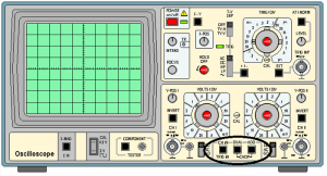
The cathode ray oscilloscope is a piece of laboratory equipment that may be used to examine the waveforms of alternating currents and voltages and measure voltage, current, power, frequency, and nearly any other variable involving amplitude and waveform. The screen displays the amplitude of electrical signals as a function of time.
It’s commonly used for troubleshooting radio and TV receivers and research and design work in laboratories. It can also be used to see how amplitude distortion and deviation from the normal affect a signal’s wave structure. The cathode ray oscilloscope has long been regarded as one of the essential tools in designing and developing contemporary electronic circuits.
What is a Cathode Ray Oscilloscope?
A Cathode Ray Oscilloscope (CRO) is a laboratory instrument that displays, measures, and analyzes electrical waveforms. A Cathode Ray Oscilloscope Is an X-Y plotter that can display an input signal vs. time or another signal.
Cathode ray oscilloscopes employ light spots created by striking an electron beam, which moves in reaction to input quantity changes. Why are we employing simply an electron beam at this time? This is because the impacts of an electron beam that can be used to track changes in the instantaneous values of a quickly changing input quantity are minimal. Cathode ray oscilloscopes work with voltages in their most basic form.
So, the voltage is the input quantity we discussed earlier. Transducers allow us to transform physical values such as current, pressure, acceleration, and so on to voltage, allowing us to visualize these numbers on a cathode ray oscilloscope. Let us now examine the cathode ray oscilloscope’s construction details.
Block Diagram of CRO
The general-purpose CRO contraction is depicted in the block diagram below. The CRO functions as a heat source for the oscilloscope and recruits the cathode ray tube. The CRT of an oscilloscope accelerates the electron beam to a high velocity and brings it to the focus point on a fluorescent screen.
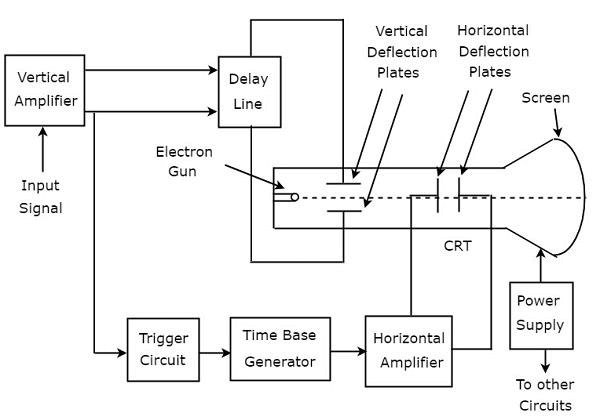
As a result, the screen creates a visible area where the electron beam collides. The electrons can operate as an electrical pencil of light, producing light where it strikes by sensing the beam above the screen in response to the electrical signal.
Different electrical signals and voltages are required to execute this activity. This serves as the oscilloscope’s power supply circuit. High and low voltage will be used in this experiment. The heater of the electron gun, which produces the electron beam, is powered by a low voltage. The beam requires a high voltage for the cathode ray tube to accelerate. Other oscilloscope control units require a standard voltage supply.
Between the electron cannon and the screen are horizontal and vertical plates that allow the beam to be detected based on the input signal. The oscillator provides a time base generator just before detecting the electron beam on the screen in the horizontal direction, which is on the X-axis, at a constant time-dependent rate. The signals are routed through the vertical amplifier from the vertical deflection plate. As a result, it can boost the signal to a level where the electron beam can be deflected.
A trigger circuit is provided if the electron beam is detected in both the X and Y axes. As a result, the horizontal deflection begins at the same place where the input signal does.
Working Principle
Because of the electrostatic field, the CRO’s working principle is based on electron ray movement. An electron beam strikes a phosphor face and produces a brilliant spot. The electrostatic energy is applied to the electron ray in two vertical directions via a Cathode Ray Oscilloscope. The action of these two electrostatic forces, which are mutually perpendicular, causes the spot on the phosphor monitor to turn. It moves to create the required waveform for the incoming signal.
Construction of Cathode Ray Oscilloscope
The construction of CRO includes the following.
Cathode Ray Tube
The CRO is a vacuum tube whose primary function is to convert electrical signals to visual signals. The electron gun and electrostatic deflection plates are both housed in this tube. The primary purpose of this electron gun is to produce a focused electronic ray with a high frequency.
The vertical deflection plate will move the electron beams from the left to the right, while the horizontal ray will turn the ray up and down. Because these operations are independent of one another, the beam can appear wherever on the screen.
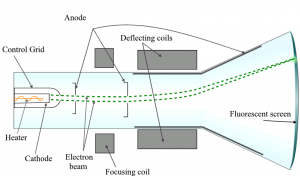
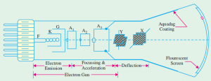
Electronic Gun Assembly
The electron gun’s primary function is to emit electrons so that they can be formed into rays. A heater, a grid, a cathode, and anodes such as accelerating, pre-accelerating, and focusing are the significant components of this cannon. Strontium and barium layers are deposited at the cathode’s end to generate high electron emissions at moderate temperatures. Barium layers are deposited at the cathode’s end.
Once the cathode grid generates the electrons, they flow through the control grid, typically a nickel cylinder with a centrally located co-axial by the CRT axis. As a result, it regulates the cathode’s generated electrons.
When electrons flow through the control grid, they accelerate due to a strong positive potential given to the pre-accelerating or accelerating nodes. The electron ray is focused on electrodes and flows via horizontal and vertical deflection plates before reaching the fluorescent light.
The accelerating and pre-accelerating anodes are connected to 1500 volts, while the focusing electrode can be connected to 500 volts. Electrostatic and electromagnetic focusing are two methods for focussing electron rays. An electrostatic focusing tube is used here on a cathode ray oscilloscope.
Deflecting Plate
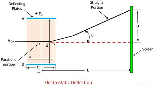
After leaving the electron gun, the electron beam will pass via the two sets of deflecting plates. This configuration produces the vertical deflection, the Y plate’s otherwise vertical deflecting plate. The plate set is employed for a horizontal deflection known as the otherwise horizontal deflection of the X plate.
Fluorescent Screen of CRT
The faceplate is the front face of a CRT television. It is flat and measures around 100mm by 100mm in size. The CRT screen is bent slightly for larger screens, and the faceplate is formed by pushing the molten glass into a mold and then heating it.
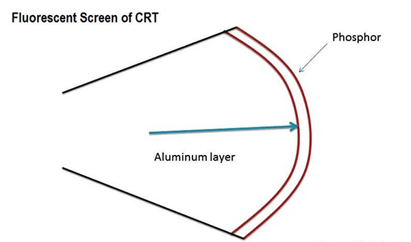
To convert energy from electrical to light, the inner face of the faceplate is coated with phosphor crystal. When an electronic ray strikes a phosphor crystal, the energy level increases, and light is produced throughout the phosphorous crystallization process, called fluorescence.
Glass Envelope
It’s a conical structure that’s been heavily evacuated. The Aquadag is used to cover the inside faces of the CRT between the neck and the display. This is a high-voltage electrode in the form of a conducting substance. To assist the electron in becoming the center, the surface of the coating is electrically coupled to the accelerating anode.
Working principle of Cathode Ray Oscilloscope
The fundamental circuit of a cathode ray oscilloscope is shown in the diagram below. We’ll go through some of the oscilloscope’s most significant features.
Vertical Deflection System
This amplifier’s primary role is to magnify a weak signal so that the amplified signal can create the desired signal. To inspect the input signals, the input attenuator and the number of amplifier stages are punctured into the vertical deflection plates.
Horizontal Deflection System
The vertical and horizontal systems both use horizontal amplifiers to boost weak input signals; however, they are not the same as the vertical deflection system. A sweep voltage penetrates the flat deflection plates, providing a time base. The synchronizing amplifier triggers the sawtooth sweep generator while the sweep selector moves to the internal position, as shown in the circuit diagram. The trigger saw tooth generator provides the input to the horizontal amplifier by following the method. The four sorts of sweeps will be discussed here.
Recurrent Sweep
As the name implies, the sawtooth is corresponding, meaning that a fresh sweep begins immodestly at the end of the previous sweep.
Triggered Sweep
Sometimes the waveform should be noted that it cannot be predicted; thus, the sweep circuit should be left inactive, and the waveform should activate the sweep under investigation. We’ll employ the triggered sweep in these circumstances.
Driven Sweep
The drive sweep is typically utilized when the sweep is free-running but is triggered by the signal under examination.
Non-Saw Tooth Sweep
This sweep is used to determine the voltage differential between the two. We can compare the frequency of the input voltages by utilizing the non-sawtooth sweep.
Synchronization
The goal of synchronization is to create a fixed pattern. The synchronization should be between the sweep and the signal. The synchronization selector can choose from various sources, which will be mentioned further down.
Internal
The vertical amplifier measures the signal, and the signal prevents the trigger from being activated.
External
The external trigger should be present in the external trigger.
Line
The power supply produces the line trigger.
Intensity Modulation
The signal is inserted between the ground and the cathode to achieve this modulation. By brightening the display, this modulation occurs.
Positioning Control
We may regulate the position of the signal and the position of the small independent internal direct voltage source by applying it to the detecting plates via the potentiometer.
Intensity Control
By adjusting the grid potential in relation to the cathode, the intensity can be altered.
Basic Controls of Cathode Ray Oscilloscope
The most basic CRO controls are positioning, brightness, focus, astigmatism, blanking, and calibration.
Position
The position control knob on an oscilloscope is mainly used to move the intense area from the left to the right side. One may easily control the spot from left to right using the knob.
Brightness
The electron’s intensity mainly determines the brightness of the ray. The control grids control the electron intensity within the electron ray. As a result, the electron ray brightness can be adjusted to manage the grid voltage.
Focus
The applied voltage toward the CRO’s central anode can be controlled to achieve focus control. The electrostatic lens is formed by the middle and other anodes in the region. As a result, by adjusting the voltage across the center anode, the main length of the lens can be altered.
Astigmatism
This additional focusing control in CRO functions similarly to astigmatism in optical lenses. The electron pathways lengths for the center and the edges are different; therefore, a ray focussed in the middle of the display would be defocused on the screen edges.
Blanking Circuit
The time base generator generated the blanking voltage in the oscilloscope.
Calibration Circuit
To calibrate an oscilloscope, an oscillator is required. On the other hand, the oscillator should produce a square waveform for the voltage provided.
Applications of Cathode Ray Oscilloscope
- CROs are utilized in large applications such as radio stations to observe the signal’s transmitting and receiving qualities.
- The voltage, current, frequency, inductance, admittance, resistance, and power factor are all measured with the CRO.
- This device is also used to test the properties of AM and FM circuits.
- This device regulates analog signals and monitors signal attributes and characteristics.
- The CRO is used to view the signal form, bandwidth, and other parameters via the resonance circuit.
- CRO can observe the shape of voltage and current waveforms, which aids in making important decisions at a radio station or communication station.
- It is used in laboratories for research. Once researchers design a new circuit, they use CRO to verify the waveforms of voltage and current of every circuit element.
- It’s used in TV, radar, and engine pressure analysis to compare phase and frequency
- It’s utilized to assess nervous and heartbeat reflexes.
- It is used to find BH curves in the hysteresis loop.
- It is possible to trace transistor curves.
Conclusion
The cathode-ray oscilloscope (CRO) has come a long way since its creation in 1897 to detect the presence of electrons. It is a necessary component of modern oscilloscopes for measuring various waveforms in electrical circuits.
The study of waveforms, transients, and time-based or frequency-based analysis is possible with an X-Y plotter, which plots an input signal against another signal or against time. We looked at how CRO works and how it may be used in this article. We hope that after reading this article, you have learned some important facts about the CRO’s operation and applications.
For more details on cathode ray oscilloscope or electrical components, contact us at ICRFQ, we manufacture the best electrical components.
If you want to find more Electronic Components Distributors, please check out the following articles:
Electronic Components Distributors In the USA
Electronic Components Distributors In UK
Electronic Components Distributors In China
Electronic Components Distributors In India
Electronic Components Distributors In Singapore
Electronic Components Distributors In Malaysia
Electronic Components Distributors In Vietnam
Electronic Components Distributors In South Korea
- Where to buy IC chips? The Best Guide? - March 26, 2024
- Breaking Down Barriers: Overcoming Obstacles in Cross-Border Electronic Component Trade - March 4, 2024
- Everything You Need to Know About Amplifier IC Chips - March 4, 2024


I am a student, and I must say that your articles are excellent.