
Last Updated on October 22, 2023 by Kevin Chen
When dealing with electricity and electric circuits, there are several terms that you should know, whether you are an electrical expert or not. One such term that you should know is continuity.
What does continuity have to do with electricity? You may wonder. In this article, we are going to analyze continuity from the electrical aspect.
What is continuity in electricity?
Continuity simply refers to the presence of a complete path through which the electric current can flow. It implies that the path is unbroken, and that there are no obstacles in it.
If you think of continuity as a physical object, then you can describe it as a tube of clear glass that has no openings or breaks in it. The current will flow from one end of the tube to the other end through this uninterrupted path.
The current cannot flow if there are breaks along the path or if parts of the tube are missing. In this case, electricity will not be able to move from one point to another point; hence continuity is a must for electrical circuits and electric currents.
If you look at a circuit diagram, you may notice that each section is linked to another section by a line called a conductor. This line is used for conducting electricity and for supplying energy from one part of the circuit to another part.
Hence, continuity should be present in each part if an electric circuit is sensitive enough so that an electric current can flow through all parts without interruption.
In the case of an alternating current, the direction of the flow will be in an alternating manner:
In a direct current, this is not the case. The direction of flow remains the same and is steady throughout.
Why is continuity important?
This is probably the first question that pops up in your mind. Why should we consider continuity as one of the most important factors in a circuit?
The first reason is the functionality of the circuit.
For example, if a circuit lacks continuity, it will not be able to function properly and deliver energy or signals. Hence all parts of the circuit should be linked via a conductor so that all electrical components in the circuit are able to receive energy or signals.
Another reason is for safety reasons. If there are parts of the circuit or sections where continuity does not exist, it will result in the problem of high voltage levels at some places and low voltage levels at other places.
This will then give rise to a high level of the voltage difference between both these points. This will result in giving rise to electrical shocks and electric shocks as well as sparking issues that can prove to be fatal.
Hence, it should be ensured that continuity is present everywhere before applying any power source to a circuit or switching on any component.
Continuity test
How can I tell that the circuit is continuous? You will have to conduct a continuity test. From the test results, you will know the state of your circuit.
Here are other important reasons for conducting a continuity test on your circuit:
To check the connection of wires in each electrical component
All electrical components like a battery and bulb are connected to each other via a wired connection. Hence, these wire connections should be checked for continuity as well so that there is connectivity between each and every component along with continuity between all places in the circuit.
To check for defects and damage at any location
There can be defects like broken or damaged wires at any place in a circuit due to which it loses its conductivity and hence have no continuity. Hence, you will have to check your circuit for such defects before applying power to it or switching on any part of it so that they are removed or repaired if required immediately.
Establish the quality of soldering
A continuity test can be used to check the strength or quality of your soldering. When you solder any wire terminations, you should ensure that they are properly and thoroughly soldered so that there is no loose connection in your circuit. But if you encounter any problem in such soldering work, a continuity test can be used to find it out and repair it by redoing the soldering work in those areas.
How to perform a continuity test
There are various ways of testing the continuity of a circuit and you can use different tools for doing the test.
One method entails using a multimeter in the continuity mode and the second method entails using an ohmmeter.
Let’s look a the steps to follow when using each of these methods.
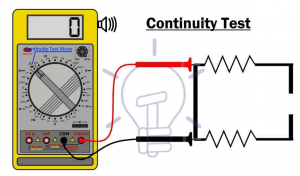
Using a multimeter in continuity mode
This is the most common method for testing and here are the steps to follow:
-Drain all the energy from the circuit if it has some power (De-energize)
-Set your multimeter to the ‘continuity mode’. This is symbolized by a sound image on the multimeter.
-Insert the black probe of the multimeter into the COM port.
-Insert the red probe of the multimeter into the V or Ω port.
-Now bring the two probes into a direct contact with each other.
-The multimeter will give you a beep sound and flash its light if the circuit is in good condition.
-If there’s no beep or flash, it means the circuit is open.
Using an ohmmeter
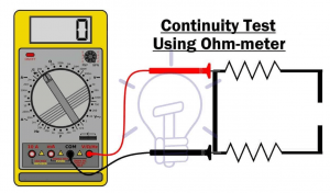
This method can help you find out if a wire is disconnected in your circuit or not. Here are the steps:
-Drain all the energy from the circuit or make sure it doesn’t have any power (De-energize)
-Turn off all power switches (OFF)
-Set your multimeter to the ‘ohms’ mode (K symbol). This symbol is used for measuring the conductivity and resistance of wires, there’s no need to set any switch here as it’s already on by default. So just turn on your ohmmeter and you’ll get ready to use it.
-Set your ohmmeter to continuity mode by using one of these switch options: By using autoranging or by setting a range value as 0 to 1.0 V (V), 10 to 20 mA (mA), or 20 to 240 mA (mA).
-Now use the black probe on the COM port and the red probe on the V or Ω port.
-Make sure you are touching only these 2 points and don’t even touch any other part of your circuit board.
-You will hear the beep sound once you connect all the probes according to their direction.
-If there’s no beep o reads 0 ohm, it means your circuit is open, if there’s a beep, it means your circuit is closed.
Doing continuity test for capacitor
You can also conduct a continuity test on a capacitor. But before you do so, first remove it from the circuit. Discharge if I was charged.
With the capacity, you can also use these methods.
Continuity mode
Even with the capacitor, the procedures are similar to the ones we have listed above. ie;
-Set the multimeter to the continuous mode
-Connect the red and black probes to the negative and positive terminals of the capacitors as required.
-If the readings start from 0 going upwards gradually, that will mean that the capacitor s good and continuous.
-A broken or damaged capacitor will display a completely low value.
Using the resistance mode
Other than the continuous mode you can also use the resistance mode to test the capacitor’s continuity. Here are the steps to follow:
-Set the multimeter to the resistance mode.
-Disconnect the capacitor from the circuit.
-Connect one of the red and black probes to any point on the capacitor.
-The other probe goes to the ground on the circuit, where it should read a nearly 0 value.
-The other option is this; connect both of the red and black probes to any point on the capacitor then connect both of them to the ground.
-If it shows a near zero resistance, that will prove that your circuit is good at short circuits
-This method works especially well for capacitors with polarized terminals such as electrolytic capacitors.
Precautions for doing a continuity test
We have just discussed various methods of conducting continuity tests However things may not be smooth as it sounds. Here are some precautions that you should take when doing the test.
-Unplug the device from the mains power source: This is a requirement before commencing the test.
-Make sure that you are using the correct voltmeter for conducting the tests.
-Do not use an incorrect voltmeter and vice versa.
-Do not be overzealous or violent when you are conducting the test.
-Use a soft material to contact the electrical terminals to prevent damage to them, which may result in poor performance of the capacitor in the circuit.
-Ensure that the capacitor is completely discharged when testing.
-Be careful about the presence of loose naked wires in the circuit.
Conclusion
I hope now you know all the details about continuity in electrical circuits and how to carry out the tests. You can now do the tests on your own on any circuit regardless of its complexity.
If you want to find more Electronic Components Distributors, please check out the following articles:
Electronic Components Distributors In the USA
Electronic Components Distributors In UK
Electronic Components Distributors In China
Electronic Components Distributors In India
Electronic Components Distributors In Singapore
Electronic Components Distributors In Malaysia
Electronic Components Distributors In Vietnam
Electronic Components Distributors In South Korea
- Where to buy IC chips? The Best Guide? - March 26, 2024
- Breaking Down Barriers: Overcoming Obstacles in Cross-Border Electronic Component Trade - March 4, 2024
- Everything You Need to Know About Amplifier IC Chips - March 4, 2024


