
Last Updated on October 22, 2023 by Kevin Chen
Electrical instruments are not directly linked to high-voltage meters or control equipment for safety concerns. Instrument transformers connect electrical appliances to measurement equipment, such as voltage and current. High-voltage, high-current instruments are converted to low-voltage, low-current instruments.
What is a Transformer?
A transformer is a device that uses mutual induction to transmit electrical energy from one circuit to another. It features two magnetically connected and electrically isolated coils, primary and secondary. They change the voltage and current levels without affecting the signal’s frequency.
Power transformers, autotransformers, isolation transformers, instrument transformers, transformers are used for specialized applications; potential transformers are two types of instrument transformers used only to measure
What is a Current Transformer?
The Current Transformer (C.T.) is an “instrument transformer” designed to produce an alternating current proportional to the current measured in its main and secondary winding. Current transformers reduce high-voltage currents to a safe level, allowing a standard ammeter to safely monitor the actual electrical current flowing in an alternating current transmission line. A basic current transformer operates on a somewhat different principle than a standard voltage transformer.
Unlike the voltage or power transformers discussed previously, the primary winding of the Current transformer has only one or a few turns. A single flat arch, a coil of heavy-duty wire wrapped around the core, or just a conductor or bus bar placed through a central hole, as shown, can all be used for this primary winding.
The main winding, which is never more than a few turns long, is in series with the current-carrying conductor supplying a load. The Current Transformer is often referred to as a “series transformer” due to this arrangement.
On the other hand, the secondary winding may contain many coils that wound on a low-loss magnetic laminated core. Because this core has a large cross-sectional area, the magnetic flux density generated by wire with a smaller cross-sectional area is low, depending on how much the current must be stepped down. It attempts to output a constant current independent of the connected load.
Until the voltage induced in the secondary is large enough to saturate the core or cause failure due to high voltage breakdown, the secondary winding will deliver current into either a short circuit, such as an ammeter, or a resistive load.
In contrast to a voltage transformer, a Current transformer’s primary current is controlled by an external load rather than the secondary load current. For larger primary current values, the secondary current is commonly rated at 1 ampere or 5 amperes.
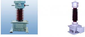
What is a Potential Transformer?
This is an instrument transformer that converts voltage between two values. This transformer reduces the voltage to a safe level that may be monitored with common low-voltage instruments such as voltmeters, wattmeters, and watt-hour meters.
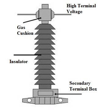
The magnetizing current is minimal because the potential transformer is made with a high-quality core that operates at a low flux density. The transformer’s terminal should be built so that the voltage ratio varies minimally with load and minimal phase shift between the input and output voltage.
The primary winding has a lot of turns, while the secondary winding has a lot less. The co-axial winding is utilized in the potential transformer to reduce leakage reactance. The insulation cost is also lowered by separating the primary winding into parts and reducing the insulation between the layers.
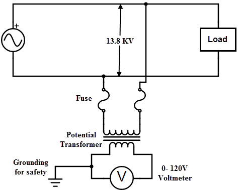
The transformer is connected in parallel with the circuit. The potential transformer’s primary windings are connected directly to the power circuit, whose voltage will be monitored. The voltmeter, wattmeter, or other measurement equipment is attached to the secondary terminals of the potential transformer.
Through the primary windings’ magnetic circuit, the secondary windings of the potential transformer are magnetically connected. The transformer’s primary terminal is rated for 400V to thousands of volts, whereas the second terminal is rated for 400V. Transformation ratio, also known as turn ratio, is the ratio of primary voltage to secondary voltage.
Current Transformers vs Potential Transformers: What’s The Difference?
Function
C.T. and P.T. transformers’ functions are among the most significant variations. On the one hand, a current transformer decreases a high current to a safer and more manageable level that can be measured. Large primary Currents are converted to little 1A/5A currents that may be monitored with an ammeter.
A potential (voltage transformer), on the other hand, measures and converts high voltage values into lower voltage levels. The high voltage is converted to a typical secondary voltage of 100V or less.
Types
Wound and closed core Current Transformers are the two types of Current Transformers. The electromagnetic and capacitor voltage potential transformers are separated into two groups.
Connection
The primary winding is linked to the transmission line, whose current is measured in the Current Transformer, and the full line current flows through the winding. Moreover, the potential transformer is wired in series with the circuit, resulting in full line voltage across the winding.
Transformation Ratio
The transformation ratio is high in a Current Transformer, whereas it is low in a potential transformer.
Primary Winding
The primary winding of a Current Transformer has fewer turns and carries the measured current. The primary winding of a potential transformer has a lot of turns and carries the voltage that has to be measured.
Secondary Winding
The secondary winding on the secondary side of a Current Transformer has many turns connected to the instrument’s current winding. The secondary winding of a potential transformer has a minimal number of turns and is connected to the meter or instrument on the secondary side.
Core
A Current Transformer is made of silicon steel lamination, but a potential transformer is a high-quality steel that can operate at low flux densities.
Primary Current
The main current in a Current transformer is independent of the secondary side circuit circumstances. The main current in a potential transformer, on the other hand, is dependent on secondary side circuit circumstances.
Use
You can combine a 5 Ampere ammeter with a Current Transformer to measure large currents up to 200 amperes. On the other hand, a potential transformer allows you to test large voltages like 11KV with a 120V voltmeter.
Secondary Side
When in service, the secondary side of a Current Transformer cannot be open-circuited. On the other hand, you can open-circuit the secondary side of a potential transformer without causing any damage.
Input Value
The input value of a Current Transformer is constant current, whereas the input value of a potential current transformer is continuous voltage.
Burden
The Current transformer does not use the secondary burden; however, the potential transformer uses the secondary load.
Applications
A Current Transformer is used for various tasks, including measuring current and power, monitoring the operation of the power grid, and operating a protective overlay. The potential transformer’s uses, on the other hand, include power source, measurement, and operating protective overlay.
The secondary side of a current transformer usually allows a short circuit but not an open circuit. A potential transformer’s secondary side, on the other hand, allows an open circuit but not a short circuit.
CT vs PT
- The current transformer transforms the instrument’s high current into a low current. Moreover, the potential transformer converts a high voltage to a low voltage.
- Stainless steel laminations are used in the current transformer’s core. The potential transformer’s body comprises a high-performance core that can operate at low flux densities.
- The measured current is carried by the primary winding of the current transformer, while the primary of the potential transformer maintains the voltage.
- The primary winding of a current transformer has a few turns, but the primary winding of a potential transformer has numerous turns.
- The current transformer’s secondary windings are numerous, and they cannot be open-circuited while the transformer is in operation. The potential transformer’s secondary winding is relatively small and may be open during the services.
- The typical voltage at the secondary winding of a potential transformer is up to 110 volts, but the standard range of a current transformer for measuring current is 5 or 1 amp. A current transformer’s transformation ratio is high, whereas a potential transformer’s transformation ratio is low.
- Current transformers are typically measured too large currents to be directly measured with a meter or instrument. On the other hand, the potential transformer determines the current’s high voltage.
- The current transformer is largely utilized in the relay protective system because it ensures that the primary current is decreased to an adequate level for relay operation. Furthermore, the current transformer protects the apparatus and employees from excessive voltage by providing insulation against the high voltage generated by the C.T. pt testing power circuit.
Last but not Least
The current transformer is mostly utilized in relay protective schemes because it decreases the high magnitude of primary current to a reasonable value for relay operation. The current transformer also protects the apparatus and employees from excessive voltage by providing insulation against the high voltage of the power circuit.
Conclusion
Finally, current and potential transformer testing guarantee that instrument transformers are in good operating order. It also guarantees that voltage and current stay within their limits. The transformers ensure that your electrical gadgets or home equipment are safe from power surges.
Lastly, for more details on the current and potential transformers, contact us at ICRFQ; we are the best electrical components manufacturer in China.
If you want to find more Electronic Components Distributors, please check out the following articles:
Electronic Components Distributors In the USA
Electronic Components Distributors In UK
Electronic Components Distributors In China
Electronic Components Distributors In India
Electronic Components Distributors In Singapore
Electronic Components Distributors In Malaysia
Electronic Components Distributors In Vietnam
Electronic Components Distributors In South Korea
- Where to buy IC chips? The Best Guide? - March 26, 2024
- Breaking Down Barriers: Overcoming Obstacles in Cross-Border Electronic Component Trade - March 4, 2024
- Everything You Need to Know About Amplifier IC Chips - March 4, 2024


