
Last Updated on October 22, 2023 by Kevin Chen
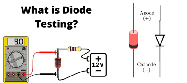
It is common knowledge that a diode is designed to work in a single direction (only allowing current flow in one direction). Under the forward-biased situation, these are expected to have very low resistance for current flow and very high resistance under the reverse-biased condition. This key attribute of the diode can be used to efficiently test the diode to determine if it is functioning correctly. In other words, diode testing can be done by measuring the electrical resistance between its terminals with a piece of equipment like a multimeter.
What Would Cause a Diode to Fail?
Short circuits, Open circuits, and unstable voltage control are the most prevalent causes of diode failure. There may be symptoms among these three sorts of failures. For example, the power supply voltage rises or falls to zero, or the output is inconsistent. As a result, individual faults must be thoroughly investigated during the diode test.
A multimeter is a typical diode measurement tool used for on-circuit (when the diode is on the circuit board) and off-circuit (when the diode is not on the circuit board) measurements. The reverse and forward resistance of the PN junction is measured in the basic concept of diode measurement, and the essential judgment is based on their values. To do well in a diode test, it is required first to comprehend the basic structure and operation of diodes, followed by an understanding of the diode’s primary failure features.
Common Diode Failures Analysis
Open Circuit
The diode’s positive and negative electrodes have been separated, and the diode’s forward and reverse resistance has become infinite. The circuit is now open once the diode is turned on.
Voltage Breakdown
This implies that a path exists between the diode’s positive and negative electrodes. The forward and reverse resistances are equal to or close to one another (but not infinite). Because there are distinct manifestations in different circuits, the activity between the positive and negative electrodes may always depart when a diode breaks down.
Forward Voltage
If the diode’s forward resistance is too high, the signal’s voltage drop on the diode will rise, causing the output signal to drop and the diode to be destroyed due to the heat. The diode’s unidirectional conductivity will deteriorate as the forward resistance increases.
Reverse Voltage
The diode’s reverse resistance decreases, causing the diode’s unidirectional conductivity to be compromised.
Performance Degradation
The diode has no visible defects in this situation, such as an open circuit or a breakdown. However, the circuit’s stability will weaken when the condition worsens, and the output signal voltage will drop.
What Is a Diode Test?
A diode is a simple two-pin gadget with an embedded electric field that transmits electric current in one way. And the diode arises from semiconductor materials. The device can be used for various tasks, including isolating signals from a source, converting AC to DC, and so on. Furthermore, the diode has two sides—n-side and p-side—that can be doped differently.
Electrons bypass the junction when a positive charge is applied to the p-side and a negative charge is applied to the n-side. The current is only moving in one direction at this moment. With that in mind, it’s critical to remember that one of the diodes’ most important properties is that conventional current only passes from one side to the other. Furthermore, electrons can only flow in one direction, from negative to positive.
So, how do you go about doing a diode test? You can begin by identifying the device’s terminals (cathode and anode). The cathode is at a nearby airport, whereas the anode is on the band’s other side. A Zener Diode’s cathode, for example, is the terminal near the black mark.
However, you can test using several approaches, such as an analog multimeter, a digital multimeter, and so on, which we’ll go into later in this post. What if you want to put a diode you built on your PCB to the test? By removing one of the diode’s leads, you can apply the methods described here.
How to Use a Digital Multimeter to Test a Diode
Diode testing with a Digital Multimeter can be done in two ways because the Digital Multimeter has two modes for checking the diode. These are the modes:
- Diode Mode
- Ohmmeter Mode (or Resistance Mode)
Because it is based on the features of the diode, the Diode Test Mode is the ideal technique to test a diode. The diode is placed in forwarding bias, and the voltage drop across the diode is measured using a multimeter in this approach. In forward bias, a usually functional diode will enable current flow and must have a voltage drop.
The reverse and forward bias resistances of the diode are measured in the Resistance Mode Test. The forward bias resistance of a suitable diode should be a few hundreds of Ohms to a few Kilo Ohms. In contrast, reverse bias resistance must be pretty high.
Procedure for Diode Mode Testing
Determine the diode’s anode and cathode terminals
- By turning the center knob to the point where the diode sign is indicated, maintain the Digital Multimeter in diode checking mode. The multimeter can provide a current of about 2mA between the test leads in this mode.
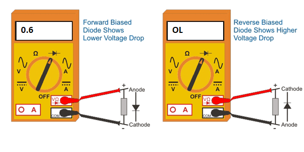
- Connect the anode with the multimeter’s red probe and the cathode with the multimeter’s black probe. In this case, the diode has a forward bias.
- Keep an eye on the multimeter’s display to see what the reading is. The diode is perfect and healthy if the voltage indicated is between 0.6 and 0.7 (for a Silicon Diode). This value falls between 0.25 and 0.3 for Germanium Diodes.
- Reverse the meter’s terminals, connecting the red probe to the cathode and the black probe to the anode. This is the diode’s reverse-biased state, in which no current passes through it. If the diode is healthy, the meter should show OL or 1 (comparable to an open circuit).
- The diode is faulty if the meter displays values unrelated to the two circumstances mentioned above. The diode’s fault may be both open or short.
- An open diode functions as an open switch in both backward and forward biased states in both bias conditions; no current flows through the diode. As a result, under both back and forward-biased settings, the meter will display OL (or 1).
- When a diode is shorted, it acts like a closed switch. This allows current flow regardless of bias and a voltage drop of 0V to 0.4V across the diode. As a result, the multimeter will show zero voltage, but the voltage drop across the diode may cause it to display a very small voltage.
Procedure for Ohmmeter (Resistance) Testing
- Like the Diode Test method, the Resistance Mode is a simple way to determine whether a diode is good, short, or open.
- Determine the anode and cathode terminals of the diode.
- Rotate the central knob or selector to the location where the ohm resistor values or symbol are indicated to maintain the Digital multimeter in ohmmeter or resistance mode. For forward bias testing, set the selector to a low resistance (about 1K ohm), and for reverse bias testing, set it to high resistance (100K ohm).
- Connect the anode to the red probe and the cathode to the black probe. This indicates that the diode is forward-biased. The resistance of the diode is extremely low when it is forward-biased.
- If the meter’s display shows a moderately low value, such as a few tens of ohms, the diode is unsuitable. But if the reading is between a few hundred ohms to a few kilo-ohms, that means the diode is suitable and working correctly.
- Reverse the multimeter’s terminals to link the anode to the black probe and the cathode to the red probe. As a result, the diode is biased in the opposite direction.
- The diode is suitable and performs properly if the meter displays a very high resistance number or OL on the meter display because the diode has a very high resistance when reverse biased.
It is evident from those mentioned above that the Digital multimeter should register some low resistance in the forward-biased position and very high resistance or OL in the reverse-biased condition for the diode to function correctly.
The diode is open if the meter reads a very high resistance or OL under both forward and reverse-biased conditions. On the other hand, the diode is considered to be shorted if the meter registers an extremely low resistance in both directions.
How to Use an Analog Multimeter to Test a Diode
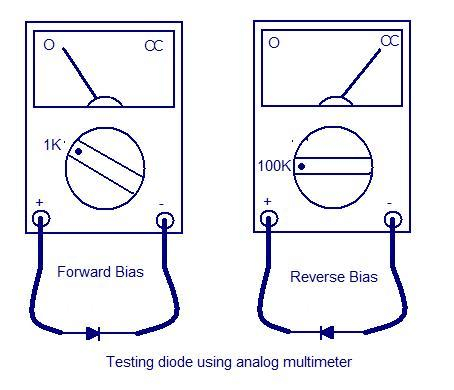
The majority of analog multimeters lack a specialized Diode Test Mode. As a result, we’ll use the Analog Multimeter’s Resistance Mode, which is analogous to utilizing the DMM’s ohmmeter mode to test diodes.
- Select a low resistance value on the multimeter selector switch.
- Connect the positive end to the anode and the negative end to the cathode to put the diode in forward-biased mode.
- The diode is healthy if the meter shows a low resistance value.
- Switch the meter’s terminals by attaching positive to the cathode and negative to the anode, with the selector in the high resistance position. The diode is said to be reverse-biased in this situation.
- The diode is perfect if the meter reads OL or high resistance.
- The diode is bad or defective if the meter fails to display the above readings.
Let’s look at how to test a Zener diode and LED
How to Test LED (Light Emitting Diode)?
As previously stated, we must first identify the pins of any diode before testing it (terminals). The length of the leads can be used to determine the LED terminals. The anode is the longer one, while the cathode is the shorter one. Another method uses the surface structure, where a flat surface represents the cathode, and a curved surface represents the anode.
Let’s look at using a digital multimeter to test an LED.
- Determine the LED’s cathode and anode terminals.
- Select diode mode on the multimeter with the selector or knob.
- Connect the meter’s probes to the LED in a forward-biased configuration.
- If the LED is functioning correctly, it will glow; if it does not, it is faulty.
- Because LED does not work in reverse-biased conditions, reverse-biased testing is impossible.
What is the best way to test a Zener Diode?
When compared to testing a regular diode, testing a Zener diode necessitates the use of additional circuitry. Since the Zener diode conducts only when the applied reverse voltage is greater than the Zener breakdown voltage, it is reverse-biased.
- The Zener diode’s terminals, anode, and cathode must be identified in the same way as a normal PN diode (using a mark).
- Join the test circuit to the power supply.
- Set the voltage mode on the multimeter’s knob.
- Connect the meter’s probes to the Zener diode.
- Increase the diode’s input supply gradually while watching the voltage on the meter screen. This meter reading should be such that as the variable supply increases, the meter output rises until the diode’s breakdown voltage is reached. Beyond this point, the meter should display a constant voltage value regardless of whether the input variable supply is increased or decreased. If this is the case, the Zener diode is in good working order; otherwise, it is faulty.
If we apply 12V from the battery through a resistor to the Zener diode (with a breakdown voltage of 6V), the multimeter should show a reading roughly equal to the 6V if the Zener diode is healthy.
Last but not least,
Understanding essential electronic components are critical, especially if you plan to create an electronic project. This allows you to detect feLeastatures in both good and bad conditions, which is an essential skill in electronic circuit troubleshooting. To put it another way, if you want the best possible results, you should perform a diode test and double-check that other critical components such as the LED, resistors, and so on are in good working order. You won’t have any problems putting the ingredients together in a PCB.
However, if you decide to put things together before checking the state of the components, it may be hard to identify the issue.
Conclusion
After all, performing a diode test isn’t difficult. However, you must first determine which type of diode you are using. After that, locate the terminals and attach them in the proper order. After that, record the results of your Digital or Analog Multimeter.
For more details on testing diode, contact us at ICRFQ. We manufacture the best electrical components in China.
If you want to find more Electronic Components Distributors, please check out the following articles:
Electronic Components Distributors In the USA
Electronic Components Distributors In UK
Electronic Components Distributors In China
Electronic Components Distributors In India
Electronic Components Distributors In Singapore
Electronic Components Distributors In Malaysia
Electronic Components Distributors In Vietnam
Electronic Components Distributors In South Korea
- Where to buy IC chips? The Best Guide? - March 26, 2024
- Breaking Down Barriers: Overcoming Obstacles in Cross-Border Electronic Component Trade - March 4, 2024
- Everything You Need to Know About Amplifier IC Chips - March 4, 2024


