
Last Updated on October 22, 2023 by Kevin Chen
Both an earth leakage relay and an earth fault relay are electrical protection devices used to safeguard humans and electrical equipment from earth leakage or faults. The fundamental difference between an earth fault relay and an earth leakage relay is that an earth fault relay is designed to detect a high earth fault current that happens when a live conductor makes direct contact with the ground.
On the other hand, the earth leakage relay is designed to detect low earth leakage current caused by indirect contact between the live portion and the earth or grounding, such as insulation failure, moisturization, and so on. Let’s take a closer look at the earth leakage and earth fault relays.
What Is the Earth Leakage Relay?
Unidentified fault currents can cause cables to overheat, perhaps causing a fire. If significant fault currents are present, hazardous voltages may emerge on earthed equipment, putting life in danger. As a result, a special protection mechanism to disconnect the energy and the load is required. For these objectives, an earth leakage relay is used.
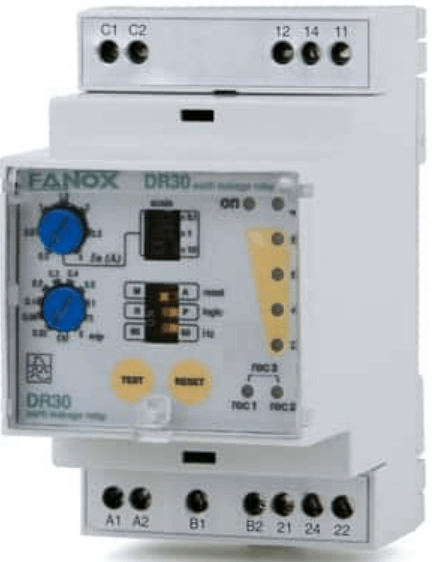
An electronic device that detects earth failures is the earth leakage relay. The earth leakage current is measured by the relay using a toroid. The earth leakage relay has a definite time operating characteristic with adjustable trip sensitivity and delay. When a fault occurs, the trip function of the relay is activated. As a result, the trip contacts in the control circuit are switched.
A toroidal transformer is required to detect the leakage current by the earth leakage relay. The toroidal transformer is built around a high-quality magnetic core to see fault currents even at extremely low levels. The various diameters adapt to different wire sections and leakage currents.
The core balance transformer enables the measurement of residual currents directly (earth leakage current). To an earth default, the presence of a homopolar component is significant. This component is measured using a toroidal transformer put around the three phases + neutral, phase + neutral, or the earth connection.
When there isn’t a problem, the vector sum of these currents is null. When an earth leakage current exists, the balance is disrupted. The vector sum of currents is no longer invalid at this point, and the toroid measures this difference.
If the neutral is spread evenly, all phases should flow through the inner half of the toroid. It is not recommended that the earthing wire runs through the toroid.
The conductor or bar to be utilized determines which toroidal transformer to use. When renovating or upgrading an existing installation, it is recommended that you use the open versions.
What Causes Earth Leakage Current?
‘Earth leakage current can occur as a result of an insulation failure in cables or equipment, or it can occur under normal operating conditions in electronic equipment that uses capacitors for filtering functions in power supply, which can produce leakage to Earth when in operation.’
How Does an Earth Leakage Relay Work?
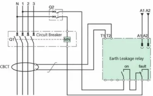
It is feasible to measure the leakage current to the earth using the earth leakage relay. A separate external toroid is used in combination with this relay. The current flow is proportional to the magnetic field created by the active conductors that pass through the toroid.
The vector sum of the current is 0 under normal conditions and in the absence of leakage current. Any fault condition results in an unbalance in the vector sum proportional to the leakage current magnitude. The toroid continuously detects the fault current’s value. The residual current relay switches its output connections when it gets a signal from the toroid. The shunt-trip then opens the circuit breaker.
Why Is an Earth Leakage Relay Needed?
Because compact residual current devices are manufactured up to 125A and have a sensitivity of up to 1000mA, we need earth leakage relays.
In circuits with larger currents, earth leakage relays can be employed. With an earth leakage relay and toroid, we can measure the leakage of a 400A–6300A busbar, but not with a compact residual current device.
A large quantity of current will flow from the live conductor to the earth if it accidentally meets the earth or ground component of an electrical circuit or device. This is known as an Earth Fault, and the fault current is also known as an Earth Fault Current. A voltage-operated earth fault relay is a device that detects earth faults. The earth fault relay is usually connected to the earth or grounding wire in series. When an earth fault occurs, a potential difference is created across the earth fault relay, which sends a signal to the circuit breaker, causing the circuit to trip or the main power supply to be disconnected.
Because an earth fault is a voltage-operated device, it can only function when many faults occur. Earth fault relays are commonly employed in electrical substations and transformer systems where a large earth fault is possible.
How Does an Earth Fault Relay Work?
As stated previously, the EFR is an earth fault monitoring device that requires input from a CT. The output tripping contacts would activate if the earth fault current remained over the specified value for the set time delay. The EFR can be utilized with a dip switch for large amperes to set the settings. The EFR’s settings, such as tripping, current, tripping, time, high peak current, and so on, can all be customized.
The operation of an EFR is similar to that of an RCCB; it follows Kirchoff’s law, which states that the current going to a place must be equal to the current coming back from that point. However, in the event of an earth fault, the current values will be drastically different, and we will utilize an EFR to locate the fault. CT will assist in determining the defect so that EFR can detect it. If the current supplied and received are the same, there will be no induced EMF in CT; if not, an EMF will be induced in CT, and the output of the EMF will be conveyed to the relay.
We can see some characteristics in EFR, such as IS, which stands for sensing current, IHS, which stands for high sensing current, and a delay, and we can use a dip switch to set all of these values in an EFR. So, if the EFR detects a fault, the trip light will illuminate, and we will need to reset the EFR after the fault has been resolved. Specific EFR models provide earth fault and overcurrent protection, while some EFRs do not include a CT; thus, we must connect one separately to the ERF.
Earth Fault Protection Devices
When an earth fault develops, the devices issue a tripping command, breaking the circuit. The Restricted Earth Fault Protection (REFP) technique limits the problem current while dispersing the fault. To determine the fault current, devices such as an earth fault relay, an earth leakage circuit breaker, and a ground fault circuit interrupter are commonly employed.
What Causes Earth Fault Current?
Faults in the Earth’s Surface: What Causes Them? The failure of the insulator is the most common cause of an earth fault in an overhead transmission or distribution line. As a result, if the insulation fails, the fault current will travel to the earth via the live conductor and metallic tower.
Earth Fault Relay VS Earth Leakage Relay
- The earth fault relay operates on voltage, whereas the earth leakage relay operates on current.
- When a significant earth fault occurs, the earth fault relay is activated. On the other hand, the earth leakage relay is activated when a small amount of earth leakage occurs.
- An earth fault relay cannot protect against electrical shock, but an earth leakage relay may.
- The earth fault relay can only work when the earth fault current passes through the earthing or grounding conductor, whereas the earth leakage relay can work when the earth leakage current flows from any point in the electrical circuit.
- The earth fault relay is less sensitive than the earth leakage relay and is a low-cost device.
- In ELCBs, earth fault relays are utilized, but in RCCBs, earth leakage relays are employed.
Final Lines
The purpose of Earth fault protection and Earth leakage protection is to detect a fault current from a phase conductor to the Earth/ground.
The difference is that Earth fault protection is generally intended to safeguard equipment. In contrast, Earth leakage protection is primarily used to protect humans from hazards such as accidental contact with a live wire or minor leakage currents caused by insulation failure.
When a live conductor directly touches the earth, the earth fault protection system kicks in. Great fault currents will flow back to the transformer through its neutral point when connected to earth in this case, which a Residual attached CTs will detect.
In Earth leakage protection, defective currents are typically measured in milliamperes or less. A Core Balance Current Transformer (CBCT) and an Earth Leakage Detecting Relay are used in the detection process (ELR).
Conclusion
An Earth Fault Relay and a Restricted Earth Fault Relay work on the same principle: when a fault current passes from a faulty section into a protective relay, the protective relay detects the fault and trips the circuit.
The earth fault relay will protect the system against any phase of an earth fault, which is the fundamental distinction between these two relays. However, it is unable to detect leakage currents going through the neutral. The restricted earth fault relay detects overcurrents or leakage currents flowing via the neutral.
For more details or purchase of other electrical components, contact us at ICRFQ. We are the best electrical manufacturers in China.
If you want to find more Electronic Components Distributors, please check out the following articles:
Electronic Components Distributors In the USA
Electronic Components Distributors In UK
Electronic Components Distributors In China
Electronic Components Distributors In India
Electronic Components Distributors In Singapore
Electronic Components Distributors In Malaysia
Electronic Components Distributors In Vietnam
Electronic Components Distributors In South Korea
- Where to buy IC chips? The Best Guide? - March 26, 2024
- Breaking Down Barriers: Overcoming Obstacles in Cross-Border Electronic Component Trade - March 4, 2024
- Everything You Need to Know About Amplifier IC Chips - March 4, 2024


