
Last Updated on April 17, 2022 by Kevin Chen
Have you ever wondered how power generation works, from the point where it is generated to when it reaches your home? Well, the electrical power system is in charge of the entire procedure. The electrical power system vocabulary is a broad phrase, but it can be broken down into three primary categories: power generation, transmission, and distribution. Although we will not be able to cover all facets of power generating in this article, we will be able to obtain a general grasp of how it works. We must first grasp electrical power before describing the electric power system.
Understanding Electric Power
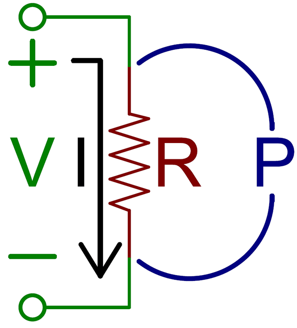
Electric power is defined as the rate at which electrical energy is moved in an electric circuit per unit of time. The product of voltage and current can be used to describe electric power. Watts are the SI unit of power. We may link electric power to mechanical power to give an intuitive perspective on how it can be intuitively sensed.
In the equation below, p stands for electric power, and Q stands for charge in coulombs. T also stands for the time in seconds. The electric current is measured in amperes, while the electric potential is measured in volts. The main difference is that the work rate is measured in watts in terms of electricity. The following is the formula for calculating work:
P=VI
Working on an Electric Power System
Let us evaluate the requirement for an electrical power system from an economic aspect before we get into the actual working. To begin, always build a generating station near readily available materials. Consumers use power, but they may be located in areas with no resources for creating electricity. Other times, various other constraints prevent the development of a generating station near densely populated areas, referred to as load centers in technical terms. We must convey the created energy to these load centers in most cases. The electric power system is the complete structure for delivering electricity efficiently and reliably, from generating plants to end customers.
The generating plants generate electricity at a low voltage level. We keep the generation voltage modest since this method has certain unique benefits. The explanation for the low voltage in the early stages of power consumption is highly clever.
Because alternators must run for long periods, the stress quotient on the alternator armature is relatively low. As a result, we may build a smaller alternator with thinner and lighter insulation for a low-voltage generation. Smaller alternators are advantageous in real-world scenarios from a technical and design standpoint. On the other hand, this low-voltage power cannot be transmitted to the load centers.
Due to low-voltage transmission, the transmission system suffers from more copper loss, poor voltage regulation, and higher installation costs. To avoid these three problems, we must step up the voltage to a certain high-voltage level. We can’t raise the system voltage beyond a particular point since the expense of insulating transmission lines skyrockets once the voltage is exceeded. As a result, the costs of the line supporting buildings skyrocket to maintain acceptable ground clearance. The transmission voltage is determined by the amount of power being sent.
Voltage step-up transformers are used to step up a system. They are equipped with the necessary safeguards and operating procedures at the power plant. The generation substation is a component of the electrical power system. We must scale down the transmission voltage to a lower level at the transmission line’s end for secondary transmission and distribution purposes.
The transmission substation uses step-down transformers and their related protection and operational measures. The electrical energy then travels through secondary or primary distribution after direct transmission. We scale down the voltage to a desired low-voltage level for distribution at the consumers’ premises after secondary transmission or main distribution.
The basic framework of an electrical power system is depicted in this comprehensive overview. We haven’t gone into detail about each piece of equipment in an electrical power system. There are several connected pieces of equipment in addition to the three primary components—the alternator, transformer, and transmission line.
The circuit breaker, lightning arrestor, isolator, current transformer, voltage transformer, capacitor voltage transformer, relaying system, controlling arrangement, line and substation equipment earthing arrangement, and many other components play an essential or critical role in the proper operation of the electric power system.
Why Do We Need an Electrical Power System?
- We always build a producing station where resources are readily available from an economic standpoint. Consumers consume electrical energy, but they may remain in areas with no resources for creating electricity.
- Not only that, but there are occasionally other obstacles that prevent us from building a generating station closer to dense consumer areas or load centers.
- Instead, we use a generator that is outside placed and then transmits the generated electricity to the load centers via a long transmission line and distribution system.
- The electric power system is the complete structure for transporting electricity efficiently and reliably from generating facilities to consumer ends.
Components of Electrical Power System
Electric power systems are energy delivery systems that deliver energy in real-time. When you turn on the light switch, power is created, produced, and supplied in real-time. Water and gas storage systems are not the same as electric power storage systems. Generators, on the other hand, produce energy when demand dictates. As a result, an electrical power system has many components.
The following are the most frequent components found in an electrical power system:
Electric power generators
Establishing the essential components of such a system is required to picture and discuss a whole functional power system. The three-phase ac synchronous generator or alternator is the first and most apparent. A prime mover must be used to drive the alternator mechanically.
Reciprocal engines and waterwheels were the primary prime movers in the early days. The hydro station with a simple waterwheel was the most straightforward sort of prime mover. The fuel was always free after the initial installation at a waterfall or dam. As a result, hydroelectric stations are rarely decommissioned. Thousands of small hydro stations are still in use today, many of which are unmanned and controlled remotely.
The steam turbine became increasingly popular when more conveniently available sources of water power were developed. Steam turbines, powered by fossil fuels like coal, gas, and oil, expanded in number and unit size until they dominated the power production sector. Even when nuclear fuels gained a significant market share, the nuclear reactor and its sophisticated heat exchanger were ultimately used to produce steam in a traditional steam turbine.
Because of the enormous fixed costs independent of capability, nuclear reactor-driven turbines must be more significant than fossil-fired units if they are economically viable. Direct energy conversion into electrical form has a bright future ahead without a spinning prime mover and alternator. Still, it is not yet cost-effective in commercial quantities.
Transformers
Due to practical design issues, the voltage level at the alternator’s terminals is kept to a minimum. The transformer is used to step up the voltage (while reducing the current) to a much greater level, allowing electricity to be transported over hundreds of miles while keeping conductor size and losses to a minimum.
A power transformer bank can be three single-phase transformers with appropriate external electrical connections or a three-phase unit housed in a single tank. The latter is more prevalent in the higher power ratings for economic reasons. The windings are frequently bathed in a special-purpose oil for insulation and cooling.
Transmission Lines
The transmission line typically consists of three conductors (single or bundles of wires) and one or more neutral conductors. However, the neutral conductor can sometimes be omitted because it simply carries the unbalanced return portion of the line current. There is no neutral return current in a three-phase circuit with properly balanced phase currents. The current is usually balanced among the phases at transmission voltages, allowing the neutral conductor to be much smaller.
The soil conditions in some places allow for an effective neutral return current through the earth. The neutral conductors have a second, equally vital purpose: they are situated above the phase conductors and serve as an excellent electrostatic lightning shield. Manufacturers of high-voltage equipment try to standardize on a few nominal voltage classes as much as feasible.
In the United States, the most common transmission line-to-line voltage classes are 115, 138, 230, 345, 500, and 765 kV. The use of voltages up to 2000 kV is now under development. Because the costs of line installation, switchgear, and transformers increase linearly with voltage, the lowest voltage class capable of delivering the projected load over the needed distance is used. The cost of energy loss, on the other hand, is inversely related to transmission voltage squared.
Circuit Breakers and Disconnect Switches
Circuit breakers are enormous three-pole switches found on both sides of big transformers and at either end of every transmission line section. The principal function of a circuit breaker is to open in the case of a fault or short circuit in the protected equipment, under the supervision of automatic protection relays.
The relays indicate the severity and likely location of the problem. They may have enough electromechanical or solid-state logic circuitry to determine whether the line or transformer can be safely re-energized and reclose the circuit breakers. A compact digital computer can analyze fault conditions and execute logical control functions in particularly important extra-high-voltage (EHV)* switchyards or substations. If the fault is transient and the system recovers, such as a lightning strike, the network’s integrity is best served by automatically restoring equipment to service, preferably within a few cycles.
If the issue persists, such as a conductor on the ground, the relays and circuit breakers will isolate the affected section. At the same time, the rest of the system continues to function normally. A circuit breaker’s secondary role is a switch that a local or remote operator can manually manipulate to de-energize a network device for maintenance.
When the contacts of a circuit breaker open under load, they tend to arc across the contact gap as it separates. Submersion of the contact mechanism in oil or gas, such as sulfur hexafluoride, is one approach used to suppress the arc (SF6). The higher voltage classes employ many interrupters or contact sets in series for each phase to extinguish the arc with a forceful air blast.
In most cases, one side of an open-circuit breaker stays activated. A disconnect switch is connected in series with a circuit breaker to completely isolate (or de-energize) it.
It’s easy to represent circuit breakers, fuses, and switches in a power system for a power system analysis. A short circuit with zero impedance is assumed when the breaker or switch is closed. An open circuit or infinite impedance is represented by a circuit breaker or open switch (or zero admittance).
Voltage Regulators
After electric power has been transferred to the location where it will be used, it must be converted back to a distribution level voltage that may be used locally. The step-down transformer bank may resemble the step-up transformer bank at the generating station, but it will only be large enough to meet the needs of the immediate region. A voltage regulator is usually connected to the output side of the step-down transformer to deliver a constant voltage to the client.
It’s a particular 1:1 transformer with multiple discrete fractional percent taps spread out over a 10% voltage range. The tap contacts will be automatically positioned by a voltage-sensing device and an automatic control circuit to accommodate for fluctuations in transmission voltage on the low side. The same effect is achieved in many circumstances by combining the regulator and its control circuitry inside the step-down transformer, resulting in a load tap changer (LTC). Tap changing under load is the term for this procedure (TCUL).
Sub Transmission
Certain intermediate voltage classes are considered sub-transmission in some systems. It was probably considered transmission when it was erected. Still, as the system grew and higher voltage transmission circuits were added, the older lines were tapped at intervals to serve more load centers and became local feeders. In most systems, sub-transmission voltages of 23, 34.5, and 69 kV are considered, and in some more extensive systems, 138 kV may also be included, depending on the application. Higher voltage classes may be consigned to sub-transmission service as the borders of higher voltages are gradually pushed back.
Distribution Systems
A low-voltage distribution system is required for the practical distribution of power to several clients in a limited region. A distribution system is a tiny version of a transmission system, with lines, circuit breakers, and transformers, but at lower voltage and power levels. Because the distinction is essentially arbitrary, electrical theory and analytical methods are similar. The voltage ranges from 2.3 to 35 kV, with 12.5 and 14.14 kV the most common. These voltage levels are commonly referred to as primary voltages, and they are stepped down to 240/120 V for most clients.
Transformers supply single-phase distribution circuits, balancing the total load on each phase as closely as possible. Three-phase distribution circuits serve only big industrial or motor loads. The ultimate transformer, which reduces the voltage from distribution to customer service level, can be located on a pole for overhead distribution systems. In contrast, it can be mounted on a pad or in a vault for underground distribution systems. Fuse or fused cuts are generally employed to protect such transformers.
Loads
Countless books have been written about the systems and processes required to produce and deliver electric power. Still, very little has been written about loads, which are responsible for all of the other components. Perhaps the fundamental reason is that loads are so diverse that they defy categorization. In the most basic sense, any electrical device is considered a burden on the system.
When seen from the source, all loads can be characterized as resistive, inductive, capacitive, or a combination of these. Loads can also be time-variant, ranging from a moderate random swing to fast cyclic pulses that create annoying flicker in nearby customers’ lights. A system’s composite load has a sizeable resistive component and a tiny net inductive component. Capacitive loads are significantly less common than inductive loads, such as induction motors.
As a result, capacitors are typically fitted in sufficient quantities to balance the majority of the inductive current to keep the resultant current as low as possible. The power utilized by a composite load on a power system has been found to vary with system frequency. In the range of typical operating frequencies (0.02 Hz), this influence is undetectable to the consumer, but it can play a significant role in the operation of synchronized systems. The load on the system varies daily and annually, posing significant operational challenges.
In the case of rotating machinery loading, power system loads can be represented as absolute power (P) and reactive power (Q) extracted from the system (as in power-flow studies), as an impedance between a system bus and ground, or as a voltage source in series with an impedance. This latter representation is critical when a rotating machine contributes to system currents during the early stages of a system fault.
Capacitors
Capacitors can be classified into transmission or distribution classes when used in a power system to reduce inductive current (power factor adjustment). They should be installed electrically as close to the load as possible. Capacitors balance out most of the inductive current component to the load when appropriately used, resulting in a load with a power factor of one. As a result, the size of the conductor required to supply a given load is reduced, and I2R losses are reduced.
Static capacitors can be employed at any voltage, but practical constraints limit the maximum voltage per capacitor to a few kilovolts. As a result, high-voltage banks must be made up of many capacitors coupled in series and parallel. A high-side circuit breaker and its related protective relays should be used to protect high-capacity transmission capacitor banks. Small distribution capacitors can be positioned in the vault or on the pole top and are protected by fuses.
Conclusion
Because of the freedom, it allows for its usage, and electrical energy has increased tremendously during the last two centuries. The range of uses has resulted in a steady increase in demand. However, as the load or demand has grown, one criterion has remained constant. We must generate the amount necessary by the load at that precise moment because such a vast amount cannot be kept to meet such high demand.
Lastly, if you need quality electrical components for good connectivity, contact us at ICRFQ. We make the best electrical components in China.
If you want to find more Electronic Components Distributors, please check out the following articles:
Electronic Components Distributors In the USA
Electronic Components Distributors In UK
Electronic Components Distributors In China
Electronic Components Distributors In India
Electronic Components Distributors In Singapore
Electronic Components Distributors In Malaysia
Electronic Components Distributors In Vietnam
Electronic Components Distributors In South Korea
- Where to buy IC chips? The Best Guide? - March 26, 2024
- Breaking Down Barriers: Overcoming Obstacles in Cross-Border Electronic Component Trade - March 4, 2024
- Everything You Need to Know About Amplifier IC Chips - March 4, 2024


