
Last Updated on October 22, 2023 by Kevin Chen
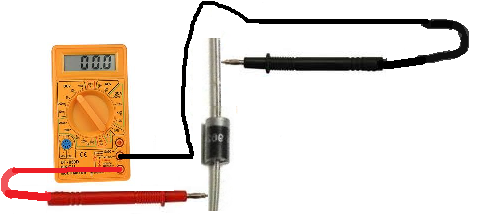
Image source: learn about electronics
Diodes are essential components in a wide range of electrical and electronic devices. They are used to control the direction of electric current and can also be used as rectifiers, allowing AC signals to be converted into DC signals.
It is important to test diodes regularly to make sure they are functioning properly, since any problems with them can have serious consequences for the device they are installed in. In this guide, we will discuss how to test a diode with a multimeter and explain the different types of tests you can perform on one.
Using a digital multimeter
In the first test, we will use a digital multimeter to test the diode
Step 1: Prepare to Test the Diode
Before you begin testing a diode, it is important to make sure you have the right equipment and that everything is set up correctly. First, make sure you have a multimeter with an Ohm setting. You will also need two leads (the probes) which should be properly connected to the multimeter. Once you have everything set up, turn the multimeter to its Ohm setting.
Step 2: Connect the Probes to the Diode
Once you have everything prepared, it’s time to connect the probes to the diode. The positive probe should be connected to the anode of the diode (the side with the long lead), while the negative probe should be connected to the cathode (the side with the short lead). Make sure both probes are securely attached to their respective sides of the diode.
Step 3: Perform a Continuity Test and Measure Resistance
Now that everything is connected, it’s time to perform a continuity test. To do this, turn the multimeter dial to its continuity setting and then touch the probes to either side of the diode. If there is a continuous connection between them, then the multimeter should beep or provide some other indication that there is in fact a connection.
Once you have done this, you can also measure the resistance of the diode. To do this, switch the multimeter to its Ohm setting and then touch the probes to either side of the diode. The resistance reading should be between 0 ohms and infinity (∞). If the reading is close to zero, then it is likely that the diode has shorted out and will need to be replaced.
Step 4: Perform a Forward Voltage Test
The final test you can perform on a diode is a forward voltage test. This involves applying a DC voltage to the diode and then measuring the current that flows through it. To do this, connect one of your leads to the anode of the diode and the other to the DC voltage source. Then, set your multimeter to its current setting and measure the amount of current flowing through the diode. This should be between 0 mA and 1 mA depending on the type of diode being tested.
Using analog multimeter to test the diode
Let’s say you have an analog multimeter. Here are the steps to follow when conducting the test. The main difference between analog and digital meters is that analog multimeters measure current by using a pointer or needle, while digital multimeters measure current electronically.
Step 1: Keep the selector switch to a low resistance value
The very first step is to ensure that the selector switch of the analog multimeter is set to a low resistance value. This setting should be indicated by either an omega (Ω) symbol or very small numbers.
Step 2: Connect the diodes in a forward-biased condition
Here you will have to ensure that the diode is connected in a forward-bias. How do I do so? By connecting the positive lead of your multimeter to the anode of the diode and the negative lead to the cathode.
Step 3: Look at meter reading
Once you have connected everything properly, look at your meter reading. A forward-biased diode should show a low resistance value on the analog multimeter, usually around 0 ohms. This indicates that the diode is in a good condition and working properly.
Step 4: Repeat the test with reverse-biased connection
Finally, repeat the same steps but this time connect the diodes in a reverse bias to see if it has any effect on meter reading. If the resistance value suddenly increases significantly, then this could indicate that the diode is faulty and will need to be replaced.
Diode mode with a digital multimeter
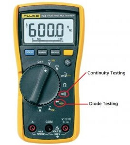
Image of diode mode:source Insttools
Another way of testing is by using the diode mode on a digital multimeter.
Diode mode refers to a special feature available in some digital multimeters (DMMs) to measure the forward voltage drop of a diode. This allows you to quickly test diodes without having to set up any external circuit and makes it much easier to compare readings across different diodes.
Step 1: Disconnect the power supply
Start off by removing the energy source from the circuit. This is majorly a safety measure that will prevent any shock or damage to the multimeter or cause any other electric-related accident during the testing process.
In case the power is derived from the capacitor, you will have to discharge it.
Step 2: Turn the “diode mode” on the digital multimeter
You can find the diode mode by scrolling through the menu options of your digital multimeter. It will be marked as “Di” or “Diode Test”.
Once you enter this mode, you will see a representation of a diode on the display and it should have two probes near it.
Step 3: Connect the probes to the diode
Now you need to connect the red and black probes from your multimeter to the diode, with one connected to the anode and other connected to the cathode.
Step 4: Observe reading
Once everything is properly set up, observe the display on your digital multimeter. If it reads “OL”, then it indicates that the diode is open and needs to be replaced. Otherwise, a reading of 0.6-0.7 volts will indicate that it is in good condition and functioning properly.
Step 5: Repeat test with reversed polarity
Finally, repeat the same steps but this time connect the probes in a reversed polarity. If the diode is in good condition, then you will see a “1” displayed on the meter. However, if you see a reading of “0L” or any other number other than 1, it could indicate that the diode is faulty and needs to be replaced.
That is all there is to it when it comes to testing a diode with an analog and digital multimeter. As you can see, both methods are fairly simple and straightforward, allowing you to quickly determine the condition of your diodes in no time.
How to test diode without multimeter
All the methods we have discussed entail using multimeter to test diodes.
Do you know that it is possible to conduct the tests without using a multimeter?
Yes, it is possible to test a diode without using a multimeter. This method is slightly more involved and requires you to use other components. Let’s discuss some of these methods:
How to test a diode with an ohmeter
An ohmeter is a device that you can use to measure electrical resistance. This is the most common method of testing a diode without using a multimeter.
Step 1: Connect ohmeter leads
Start by connecting the ohmeter leads to either side of the diode, with one lead connected to the anode and other connected to cathode.
Step 2: Set ohmeter to resistance mode
Now you need to set the ohmeter to resistance (R) mode. This will allow you to measure the electrical resistance of the diode.
Step 3: Read reading
Once everything is set up, observe the display on your ohmeter. If it reads a high value, then this indicates that the diode is in good condition and functioning properly. On the other hand, if it reads a low value then it means that the diode is faulty.
How to test a diode using a bulb
This method involves using a small bulb to check the condition of diodes.
Step 1: Connect circuit
Start off by arranging the components in an L-shaped circuit, with one side connected to the diode and other side connected to a small bulb.
Step 2: Turn on power supply
Now you need to turn on the power supply and observe the output from the bulb. If it lights up, then this indicates that the diode is functioning properly. However, if it does not light up then it means that the diode is faulty and needs to be replaced.
Replace your faulty diodes
After the tests and diagnosis, if your diodes are in fact faulty then it is important to get them replaced as soon as possible. This can be done either by yourself or with the help of a professional.
Ensure that you buy high-quality diodes from reputable suppliers and manufacturers. And this is where ICRFQ comes in.
We are a reputable supplier of diodes in China. Whether you need a single diode or a bulk order, we have got you covered. We take pride in providing our customers with top-notch diodes at competitive prices in China. Contact us for the best deals.
If you want to find more Electronic Components Distributors, please check out the following articles:
Electronic Components Distributors In the USA
Electronic Components Distributors In UK
Electronic Components Distributors In China
Electronic Components Distributors In India
Electronic Components Distributors In Singapore
Electronic Components Distributors In Malaysia
Electronic Components Distributors In Vietnam
Electronic Components Distributors In South Korea
- Where to buy IC chips? The Best Guide? - March 26, 2024
- Breaking Down Barriers: Overcoming Obstacles in Cross-Border Electronic Component Trade - March 4, 2024
- Everything You Need to Know About Amplifier IC Chips - March 4, 2024


