
Last Updated on October 22, 2023 by Kevin Chen
A typical vehicle encompasses an array of different electronic components. The lighting system and even the sound system are just some of these components. When one of these components develops a problem, it can be quite difficult to diagnose the exact issue, unless you are an expert.
But in most cases, the problem could be related to the relay. In this article, I will guide you on how to test a relay using a multimeter.
What is a relay?
A relay is an electrical component that takes the input of a voltage and outputs a different voltage that is suitable for the output of another component.
One of the most common uses of relays is to switch on and off lights, fans, or any other electronic component.
The relay could be connected to multiple components, which means that it can be used for multiple functions.
How does a relay work?
A relay works by using electromagnetism. When you have an electric current flowing through it, it will create an electromagnetic field. This electromagnetic field will then attract or repel the magnet in another component called “the armature”.
This repulsion or attraction will then activate the circuit which will cause the relay to switch on the component.
The connection of a relay is usually done with a “wiring” system. This wiring system is a series of wires that connect the relay to the circuit. The wiring system is usually made up of “wires” that are connected with small pins or balls that are called “poles”.
Why should I test a relay?
When testing a relay it is important to make sure that the relay is working properly. A relay can be damaged by being in an area of high heat or electrical current.
If you are not sure if your relay is working properly, then it would be best to test it.
Safety measures when testing relay
Testing a relay with a multimeter is a simple process. However, this does not mean that you throw caution to the wind. With electricity, anything bad can happen.
Here are some of the safety precautions that you should take when testing relays;
-Handle the relay with utmost care; it is made of electrical parts and it could be dangerous if touched wrongly.
-Be sure that the circuit you are working on is not powered by any electricity.
-When testing a relay, do not touch the armature and do not touch the pins of the relay with your fingers, this could cause electric shocks.
-Do not expose a relay to high temperatures; this can damage it.
-If you are testing a relay that has been damaged, do not use it until it has been fixed or replaced by an engineer.
-Don’t mix up the relays; of different electrical components.
What tools do I need?
Testing a relay is not something that you can do on your own, as it requires some knowledge of electronics and electrical wiring.
If you have the right equipment, then you can test a relay by yourself. You will need the following;
-A multimeter or voltmeter; is used to measure voltages and currents in circuits and is useful for testing relays. In our case, we will use a multimeter.
-A screwdriver to remove the cover of the relay.
-A woodblock to hold the relay when testing it.
Steps of testing the relay
Here are the steps you should follow when testing the relay:
Step 1: Locate the relay
Relays are found in different parts and components of a vehicle. So the first step of the testing process will entail locating its exact point. It can be found in the ECU, on the dashboard, or under the hood.
Step 2: Remove the relay from its housing
To remove a relay from its housing, you have to unscrew it from the metal plate that holds it.
It is easier if you have a screwdriver with a long handle (a Phillips screwdriver) to remove the cover of the relay.
If you do not have a screwdriver with a long handle, then use your fingers and pry it out using some force. Once you have removed the cover of the relay set it aside and proceed to step 3.
Step 3: Test the relay
Once you have located the relay and removed its cover, you will be able to test it.
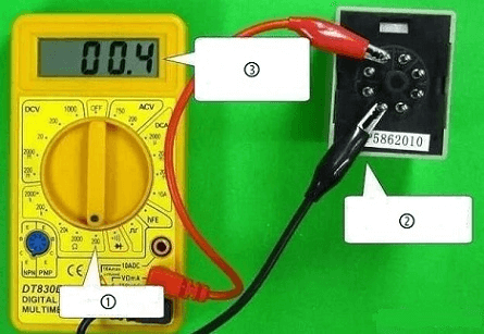
Here you will use the multimeter to check whether there is a current flowing through the coil of the relay or not.
To do this, place your multimeter on the Ohms scale and apply 11V to the coil of the relay. The reading should be zero.
If there is no current, then it means that there is no power flowing through the coil.
If there is a current, then it means that power is flowing through it.
To check the relay, you will have to use your multimeter to measure the resistance.
Set the multimeter on the Resistance scale and apply 11V to the coil of the relay. The reading should be zero and you can proceed to step 4.
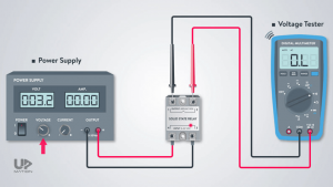
Step 4: Check the switch
To check the switch, you will have to use your multimeter.
Set the multimeter on the Resistance scale and apply 11V to the switch. The reading should be zero.
If there is a current, then it means that power is flowing through the switch. If there is no current, then it means that there is no power flowing through the relay.
To test the switch, you will have to use your multimeter to measure the resistance. Set the multimeter on the Resistance scale and apply 11V to the switch. The reading should be zero and you can proceed to step 5.
Step 5: Test whether there are any faults with relays or switches
If there is no current, then it means that there is no power flowing through the relays.
If there is a current, then it means that power is flowing through the relays.
To check the switches, you will have to use your multimeter to measure the resistance.
Step 6: Check whether there are any faults with relays or switches
If there are no faults, then it means that all of your relays and switches are working fine and you have successfully wired your circuit up. If you find any faults in any of your components, then you can proceed to step 7.
Step 7: Fix all the faults
If there are no faults, then you have successfully wired your circuit up. If you have found any faults in any of your components, then you can proceed to step 8.
Step 8: Test whether all the components are working properly
If there are no faults, then it means that all of your relays and switches are working fine and you have successfully wired your circuit up.
Tips when using a multimeter to test the relay
Other than the above steps here are some tips that will make your work easier when it comes to testing the relay.
-Use your vehicle’s service manual; this will help you with the wiring diagrams and the pinouts of the relay.
-Read your circuit’s schematic; this will help you to understand which pins of the relay are connected to which circuit.
-Make sure that you have tested all your components before proceeding to test the relay.
-Test all your relays before testing one by one.
-Make sure that all your relays are correctly wired and there is no short circuit between any of them.
-Use a multimeter with a minimum range of 200 V to measure the resistance between pins and coils of the relay.
-Always test the relay from the same side (i.e. positive or negative).
-Do not test the relay in a circuit with other relays without proper isolation.
-Make sure that the relay is correctly wired and there is no short circuit between any of them.
What should I do if the relay is found to be faulty?
After testing, you may discover that the relay has some serious faults. So What should you do?
If the fault is very minor, you may consider replacing the relay. The relay will cost less than $1 and a defective relay can affect the whole system.
If the fault is major, you may consider replacing all relays except for that one.
If the fault is very minor, you may consider replacing all relays except for that one.
The cost of a faulty relay can be as high as $50-$100 each. If your entire system has 10 relays, it will cost about $500-$600 to replace them all, which is expensive!
Conclusion
I hope you found this article useful. If you have any questions, please leave a comment and I will try to answer them as soon as possible. And in case you would like to buy relays let ICRFQ be your partner. We have a wide range of products that can be used for relays. ICRFQ is a reliable company and we will do our best to help you.
If you want to find more Electronic Components Distributors, please check out the following articles:
Electronic Components Distributors In the USA
Electronic Components Distributors In UK
Electronic Components Distributors In China
Electronic Components Distributors In India
Electronic Components Distributors In Singapore
Electronic Components Distributors In Malaysia
Electronic Components Distributors In Vietnam
Electronic Components Distributors In South Korea
- Where to buy IC chips? The Best Guide? - March 26, 2024
- Breaking Down Barriers: Overcoming Obstacles in Cross-Border Electronic Component Trade - March 4, 2024
- Everything You Need to Know About Amplifier IC Chips - March 4, 2024


