
Last Updated on October 24, 2023 by Kevin Chen

In electrical installations, isolators and circuit breakers are commonly utilized. However, they serve various purposes. The differences between the two will be discussed in this article. Continue reading to find out more about them.
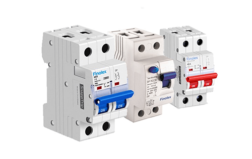
What is an isolator, and how do they work?
The isolator is a sort of mechanical switch used to separate a portion of an electrical circuit when needed. When there is no load on an electrical circuit, isolator switches are used to open it. It’s not a good idea to open it when the line is active. Typically, these are used on both ends of the circuit breaker, making circuit breaker repair simple and risk-free.
While the system is offline/online, an electrical isolator isolates any form of an electrical component from the system. The isolator doesn’t have a method to prevent arching during disconnecting. An electrical isolator switch, similar to one found in an electrical substation, is mostly used to disconnect a power transformer once it is in a no-load state unless a little load is present. Isolators don’t work when there’s a lot of traffic.
The operating idea of an electric isolator is extremely simple because it can be operated manually, semi-automatically, or fully automatically. These are sometimes employed as switches, referred to as electrical isolator switches. Depending on the situation, this switch can be opened or closed. However, in some cases, such as transformers, electrical transmission lines, and grid stations, these are permanently arranged in a fixed location to preserve isolation.
An electrical isolator switch is a device used to isolate a circuit by maintaining and inhibiting current flow. These switches are found in various electrical appliances, including kitchen appliances, power grids, and so on. Single-pole, double-pole, 3-pole, 4-pole, fused, and battery isolator switches are among the several types of isolator switches available.
If the electrical isolator does not have an arc quench mechanism, it should be used once there is no potential of current passage throughout the circuit. As a result, no live circuits must be open; otherwise, the isolator procedure will close them.
A complete live closed-circuit should not be opened through the isolator process to avoid excessive arcing among isolator contacts. Moreover, a live circuit should not be closed. As a result, isolators should be open once the circuit breaker is turned on. In the same way, the isolator must be turned off after the circuit breaker has been turned off.
An isolator can be operated locally or through a mechanical mechanism from a remote place. Because the motorized operation is more expensive than manual operation, a decision must be made before selecting an electrical isolator for the system that operates manually or mechanically is optimal.
Manually operated isolators can be used with systems up to 145 kV, whereas motorized isolators are used with high voltage systems up to 245 kV or 420 kV.
What is a Miniature Circuit Breaker?
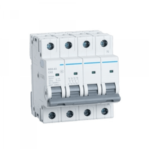
A microcircuit breaker, or MCB, is an electromagnetic device encased in molded insulating material. The major function of an MCB is to switch the circuit, i.e., to open the circuit (which has been connected to it) automatically, when the current flowing through it (MCB) exceeds the value at which it is set. If necessary, it can be turned on and off manually, just like a standard switch.
The size of the overcurrent controls the operating time of MCBs, which are time-delay tripping devices. This means that these are activated whenever an overload lasts long enough to threaten the circuit under protection.
As a result, MCBs aren’t affected by transient loads like switch surges or motor starting currents. In most cases, they’re designed to operate in less than 2.5 milliseconds for short circuit failures and 2 seconds to 2 minutes during overloads (depending on the current level). An MCB is a molded insulating material that encases a whole enclosure. This ensures that the housing is both mechanically and thermally sound.
Incoming and outgoing wires are connected to a fixed and movable contact in the switching system. Depending on the circuit breaker’s rating, the metal or current-carrying portions are electrolytic copper or silver alloy.
In the event of an overload or short circuit, an electric arc forms as the contacts separate. Modern MCBs are built to handle arc interruption operations involving metallic arc splitter plates for arc energy extraction and cooling.
An insulating substance keeps these plates in place. Arc runner is also included to push the arc created between the primary contacts. Magnetic and thermal tripping systems make up the operational mechanism.
A composite magnetic system with a spring-loaded dashpot and a magnetic slug in a silicon fluid, as well as a regular magnetic trip, make up the magnetic tripping setup. A current-carrying coil pushes the slug against the spring towards a fixed pole piece in the trip arrangement. When the coil produces a significant magnetic field, the magnetic pull on the trip lever develops.
Regardless of the location of the slug in the dashpot, the strong magnetic field produced by the coils (Solenoid) is sufficient to attract the armature of the trip lever in case of short circuits or heavy overloads.
The thermal tripping setup consists of a bimetallic strip around which a heater coil is coiled to generate heat based on current flow. The heater can be direct, with current flowing through a bimetal strip that affects a portion of the electric circuit, or indirect, with current flowing through a coil of current-carrying conductor looped around the bimetallic strip. In the event of particular overload conditions, the deflection of a bimetallic strip initiates the tripping mechanism.
Bimetal strips are made up of two metals, typically brass and steel. Along their length, these metals are riveted and welded together. Normal currents do not cause the strip to heat up to the point of tripping, but if the current exceeds the rated amount, the strip will be warmed, bent and the latch will be triggered. Bimetallic strips give certain time delays in response to specific overloads.
Structure of Miniature Circuit Breaker
Operating mechanisms, contacts, protective devices (different releases), arc extinguishing systems, and other components make up miniature circuit breakers.
Contacts
The role of the moving and static contacts is to make or break the circuit before and after it fails. The technical requirement of the small circuit breaker contact is to make and break the limit short-circuit current and the circuit current below it stably and reliably. At the same time, it requires a current capable of long-term operation, with no significant wear and tears after the action has been completed within the required service life.
Arc Extinguishing System
When the contacts are removed from each other, the arc extinguishing system is used to extinguish the arc. The arc extinguishing system comprises two parts: one is a strong spring mechanism that allows low voltage circuit breakers’ contacts to be separated fast, and the other is an arc extinguishing chamber situated above the contacts. The arc extinguishing chamber’s grille detects a high magnetic field when the main contact is removed. The arc is drawn into the grid and burned out in phases to safeguard the contacts from harm.
Protective Device
Microcircuit breakers frequently use trippers to protect the distribution system, such as Undervoltage, excitation, and overcurrent trippers. Undervoltage protection monitors the magnitude of operational voltage fluctuations using Undervoltage trippers built into micro circuit breakers.
When the voltage lowers to 70% to 35% of rated voltage or a fault occurs, it feeds back to the circuit breaker and conducts an urgent breaking action, preventing the circuit breaker from closing if the voltage dips below 35%.
Operating Mechanism
Magnetic and thermal trips are used to operate the microcircuit breaker. The magnetic trip device comprises a composite magnetic system with a spring-loaded buffer and a magnetic spring plug in the silicon fluid, and a standard magnetic stripe. A bimetal strip surrounds the thermal tripping mechanism, and the heater coils are coiled around it to generate heat based on current flow.
Differences between Isolator and MCB
The following are the distinctions between an isolator and an MCB.
Definition
The isolator is a device that isolates the load from the main power supply. An MCB is a circuit breaker that protects electrical cables from the harmful consequences of high currents. Although the MCB trips the circuit, the open contact of the MCB cannot be seen from the outside.
(Handle may be damaged) As a result, it is not advisable to touch any electrical circuit by turning off the MCB. An isolator is required for increased safety. The isolator is a mechanical switch that isolates a portion of the circuit from the rest of the system to do maintenance safely. In electrical installations, isolators create, carry, and interrupt circuit current.
Protection and Isolation
The protective function is the major distinction between an isolator and an MCB. There is no protection function on the isolator.
It serves as an electrical circuit’s isolating switch. Overload and short circuit protection are provided by MCBs (miniature circuit breakers). It also can isolate itself.
Maintenance
Although the MCB trips the circuit, the open contact of the MCB cannot be seen from the outside. (Handle may be damaged) As a result, it is not advisable to touch any electrical circuit by turning off the MCB. An isolator is required for increased safety. The isolator is a mechanical switch that isolates a portion of the circuit from the rest of the system to do maintenance safely. Isolators are used to create, transport, and interrupt circuit current in electrical installations.
Location in The Circuit
Isolators are frequently utilized as a house’s main switch. Isolators are used in residential, commercial, and industrial applications to switch under load (even inductive). Their major purpose is to make it possible to maintain the electric system safely. They also ensure that the downstream circuits are completely insulated. Upstream protection against short circuits and overloads is required for isolators.
Conclusion
The circuit breaker and the isolator are used to turn the electrical appliance on and off. This means that they both function as a single switch. The isolator is often referred to as an unloading device. The circuit breaker is also referred to as an on-load device.
Because it can only operate under closed load, the isolator is an off-loading device. This signifies that the isolator cannot be closed under any current circumstance. If you carefully study the user handbook for the isolator, you will notice that it is not to be utilized in the power-on state.
Lastly, at ICRFQ, we are the best electrical components manufacturer in China. If you need any electrical components, contact us.
If you want to find more Electronic Components Distributors, please check out the following articles:
Electronic Components Distributors In the USA
Electronic Components Distributors In UK
Electronic Components Distributors In China
Electronic Components Distributors In India
Electronic Components Distributors In Singapore
Electronic Components Distributors In Malaysia
Electronic Components Distributors In Vietnam
Electronic Components Distributors In South Korea
- Where to buy IC chips? The Best Guide? - March 26, 2024
- Breaking Down Barriers: Overcoming Obstacles in Cross-Border Electronic Component Trade - March 4, 2024
- Everything You Need to Know About Amplifier IC Chips - March 4, 2024


