
Last Updated on October 22, 2023 by Kevin Chen

LC circuit image source Wiki
An LC circuit, also known as a resonant circuit, is an electric circuit consisting of an inductor (L) and a capacitor (C). This type of circuit is used to store and release electrical energy and is commonly found in radios, televisions, and other electronic devices. The LC circuit has many applications, such as in filters, oscillators, and signal processing. It is also used in the design of antennas and other wireless devices. The LC circuit is an important part of many electrical and electronic systems.
In this guide, we are going to discuss everything about LC circuit: their components, and how it works.
We will also guide you on where to buy the LC circuit’s electronic components in China.
History of LC Circuit
The concept of an LC circuit was first developed in the late 1800s by German physicist Heinrich Hertz. He was studying how electrical signals propagate through air, and observed that capacitors and inductors could store energy when connected together in a circuit.
The LC circuit was later used in the development of radios and other electronic devices. Today, LC circuits are used in a variety of applications, from home electronics to aerospace systems.
What makes up an LC circuit?
An LC circuit consists of an inductor and a capacitor connected in parallel or series. The inductor stores energy in the form of a magnetic field, while the capacitor stores energy in the form of an electric field.
The two components interact with each other in such a way that creates an oscillating current.
The inductor typically has an inductance value measured in henries, while the capacitor typically has a capacitance value measured in farads.
The frequency of oscillation in the LC circuit is determined by the LC time constant, which is equal to the product of the inductance and capacitance values.
How does an LC circuit work? Complete guide
The working principle of an LC circuit, also known as an inductor-capacitor circuit, is based on the storage of energy in a magnetic field created by a coil of wire, known as an inductor, and in an electric field created by a capacitor.
The circuit is composed of an inductor, represented by the symbol L, and a capacitor, represented by the symbol C, connected together in series or parallel.
When a voltage is applied to the circuit, a current flows through the circuit and charges the capacitor.
The stored energy in the capacitor is then transferred to the inductor, where it is stored in a magnetic field.
As the capacitor discharges, the magnetic field in the inductor collapses, inducing a voltage in the coil that is opposite in polarity to the applied voltage.
This process continues in a cycle, allowing the circuit to oscillate as long as energy is supplied to the circuit.
The frequency of oscillation is determined by the inductance and capacitance of the circuit.
At the same time, the impedance of the circuit is determined by the inductance and capacitance of the circuit, which can be used to filter out certain frequencies.
Series LC Circuit Resonance arrangement

Series LC: Image source Linquip
A series LC circuit (sometimes known as a resonant circuit, tank circuit, or tuned circuit) is an electrical circuit consisting of an inductor and capacitor connected in series.
It is a type of electrical circuit that is used to filter out certain frequencies and allow others to pass through.
When the inductor and capacitor are connected in series, the circuit forms a resonance, which is a phenomenon that occurs when the inductive and capacitive reactances of the components are equal and opposite.
The resonance frequency of the circuit is determined by the values of the inductor and capacitor, and can be adjusted by changing either or both.
The series LC circuit is a basic building block of many electronic systems and is used in a variety of applications, from radio receivers to power supplies.
The total voltage in this arrangement will be determined by the sum of the voltages across the inductor and the capacitor, which will be equal to the voltage applied to the circuit.
It is indicated by the formula Vt = Vl + Vc
The total current in this arrangement is determined by the sum of the currents through the inductor and the capacitor, which will be equal to the current applied to the circuit.
It is indicated by the formula It = Il + Ic
At resonance, the inductive reactance and capacitive reactance of the series LC circuit are equal and opposite, and the total impedance of the circuit is at a minimum.
The resonance frequency of the circuit is determined by the values of the inductor and capacitor, and can be adjusted by changing either or both.
The power dissipated in a series LC circuit is determined by the product of the total voltage and current, and is equal to the power that is applied to the circuit.
It is indicated by the formula Pt = Vt * It
The quality factor of a series LC circuit is determined by the ratio of the total stored energy to the total dissipated energy. The higher the quality factor, the better the resonance.
The quality factor is indicated by the formula Q = 1 / R * (1/ (2πf × L) + (1/ (2πf × C))) where R is the total resistance of the circuit, f is the resonance frequency, L is the inductance of the inductor, and C is the capacitance of the capacitor.
Parallel LC Circuit Resonance f
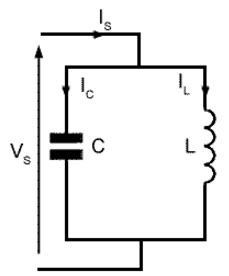
Image source Linquip
A parallel LC circuit is a type of resonant circuit composed of an inductor and a capacitor connected in parallel.
The circuit is used to create a resonance at a certain frequency, which can be used to filter out certain frequencies or amplify them.
The resonance frequency is determined by the values of the inductor and capacitor and is given by the equation:
f = 1/(2π√LC)
where f is the resonance frequency, L is the inductance of the inductor, and C is the capacitance of the capacitor.
To set up the circuit, connect the capacitor and inductor in parallel, then connect the two components to a power source.
The power source should be able to provide enough voltage to support the resonance frequency.
Once the circuit is connected, adjust the frequency of the power source until the resonance frequency is reached.
At this point, the current flowing through the circuit will be at its highest, and the voltage across the capacitor will be at its peak.
The resonance frequency of the circuit can be adjusted by changing either the value of the inductor or the value of the capacitor.
Increasing the inductance will increase the resonance frequency, while decreasing the capacitance will decrease the resonance frequency.
The parallel LC circuit has a number of applications, including radio transmitters, receivers, and filters. It can also be used to create high-Q oscillators, which are used in precision timing applications.
Applications of LC Circuits
Both the series LC circuit and parallel LC circuits have various applications.
- Band-Pass Filters: LC circuits are used in the design of band-pass filters which allow signals of a specific frequency range to pass and reject signals of other frequencies. The LC circuit is used as a resonator in these filters.
- Tuned Amplifiers: LC circuits are used to tune amplifiers by adding a capacitive or inductive reactance to the input or output circuits of the amplifier. This helps in amplifying only signals of specific frequencies while rejecting signals of other frequencies.
- Oscillators: LC circuits are used in the design of oscillators which are circuits that generate a periodic electrical signal. The LC circuit acts as a resonator in these oscillators which produces a sinusoidal output.
- Radio Receivers: LC circuits are used in radio receivers for tuning in to specific frequencies. They are used to shape the frequency response of the receiver, allowing it to select a particular frequency.
- Surge Protectors: LC circuits are used in surge protectors to limit the amount of current that flows in the circuit. The inductor in the LC circuit absorbs the excess energy, thus preventing damage to the circuit.
- Delay Lines: LC circuits are used in the design of delay lines which are circuits used to delay the propagation of signals. The LC circuit serves as the resonator in these lines which produces a phase shift in the signal.
Resonance effect of the LC circuit
The resonance effect of an LC circuit refers to the increase in energy stored in the circuit when its frequency is tuned to the resonant frequency of the circuit.
The resonance effect is caused by the interaction between the inductor and the capacitor in the LC circuit.
When the frequency of an external signal is applied to the LC circuit, it causes the current to oscillate between the capacitor and the inductor. T
his oscillation creates an electrical field around the components, which increases the amount of energy stored in the circuit.
This increased energy can be used to power other electronic components, such as a radio transmitter or receiver.
The resonance effect of an LC circuit is important for the design of electrical circuits, as it can be used to increase the efficiency of the circuit by increasing the amount of energy stored in it.
What is the order of LC circuit?
The order of an LC circuit is determined by the number of inductors and capacitors connected in the circuit.
An LC circuit is composed of a capacitor, an inductor and a resistor.
The order of an LC circuit is determined by the number of inductors and capacitors connected in the circuit.
For example, if there are two inductors and one capacitor, the order of the LC circuit will be 2.
If there are two capacitors and one inductor, the order of the LC circuit will be 1. The LC circuit order is calculated by the formula:
Order = Inductors + Capacitors – 1
For example, if there are three inductors and two capacitors connected in the LC circuit, the order of the circuit will be 4.
The order of an LC circuit is important in determining the resonant frequency of the circuit.
The resonant frequency is determined by the formula:
f = 1/2π√LC
Where, f = resonant frequency L = total inductance C = total capacitance
The resonant frequency of the LC circuit will vary according to the order of the circuit. Higher-order LC circuits will have higher resonant frequencies.
LC circuit problems
Despite their efficiency, there are numerous problems associated with the LC circuits. Let’s discuss some of them and how they are solved.
1. Waveform Distortion: The waveform generated by an LC circuit can become distorted due to the inductive and capacitive reactance present in the circuit. This effect is most pronounced when the input frequency is close to the resonant frequency of the circuit. To solve this problem, an additional inductor or capacitor can be added to the circuit to reduce the distortion.
- Tuning Problems: Due to the inherent inductance and capacitance of the components in the LC circuit, it can be difficult to accurately tune the circuit. We can solve this problem by using a variable inductor or capacitor, which allows the user to fine-tune the circuit to exactly the desired frequency.
- Parasitic Oscillations: If the capacitance and inductance in the LC circuit are not properly matched, parasitic oscillations can occur, which can cause the circuit to become unstable and produce incorrect results. To solve this problem, the capacitance and inductance of the components must be adjusted until the circuit is stable and produces the desired results.
- High Impedance: The high impedance of the LC circuit can cause problems if it is used in an application that requires high current. To solve this problem, anadditional resistor canbe added to the circuit to reduce the impedance and increase the current.
- High Frequency Loss: Due to the high-frequency losses in the LC circuit, it is not suitable for use in applications that require high-frequency signals.
Conclusion
Now that you know all about LC circuits, you can go ahead and implement them in your applications. If you would like to buy electronic components for LC circuits in China, consider choosing ICRFQ.
We are a reputable supplier with a large selection of high-quality components at competitive prices. Contact us and we are ready to serve you.
If you want to find more Electronic Components Distributors, please check out the following articles:
Electronic Components Distributors In the USA
Electronic Components Distributors In UK
Electronic Components Distributors In China
Electronic Components Distributors In India
Electronic Components Distributors In Singapore
Electronic Components Distributors In Malaysia
Electronic Components Distributors In Vietnam
Electronic Components Distributors In South Korea
- Where to buy IC chips? The Best Guide? - March 26, 2024
- Breaking Down Barriers: Overcoming Obstacles in Cross-Border Electronic Component Trade - March 4, 2024
- Everything You Need to Know About Amplifier IC Chips - March 4, 2024


