LM358DR
Part Number: LM358DR
Manufacturer: Texas Instruments
Description: Operational Amplifiers
Shipped from: Shenzhen/HK Warehouse
Stock Available: Check with us
ICRFQ.com - Electronic Components Distributor in China Since 2003

We make your sourcing easier!
Get A Fast Quote Worldwide!

Part Number: LM358DR
Manufacturer: Texas Instruments
Description: Operational Amplifiers
Shipped from: Shenzhen/HK Warehouse
Stock Available: Check with us
| Category | Integrated Circuits (ICs) |
|---|---|
| Family | Linear – Amplifiers – Instrumentation, OP Amps, Buffer Amps |
| Manufacturer | Rohm Semiconductor |
| Series | Trophy |
| Packaging | Tape & Reel (TR) |
| Part Status | Active |
| Amplifier Type | General Purpose |
| Number of Circuits | 2 |
| Output Type | – |
| Slew Rate | 0.3 V/μs |
| Gain Bandwidth Product | 700kHz |
| -3db Bandwidth | – |
| Current – Input Bias | 20nA |
| Voltage – Input Offset | 3mV |
| Current – Supply | 1mA |
| Current – Output / Channel | 30mA |
| Voltage – Supply, Single/Dual (±) | 3 V ~ 32 V, ±1.5 V ~ 16 V |
| Operating Temperature | 0°C ~ 70°C |
| Mounting Type | Surface Mount |
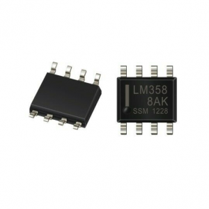
| Package / Case | 8-SOIC (0.154″, 3.90mm Width) |
| Supplier Device Package | 8-SOIC |
The integrated circuit, often known as an IC, is a tiny black chip that is both a foundational element of modern electronics and an indispensable part of most electronic circuits. Integrated circuits have various uses, including in electronic circuit boards, embedded systems, and other electronic projects. An integrated circuit collects distinct electrical and electronic components such as resistors, capacitors, and transistors.
ICs are used in many electronic devices. One single chip contains each of these individual components incorporated into it. They are available in various formats, including 555 timers, single circuit logic gates, voltage regulators, microprocessors, microcontrollers, and op-amps such as LM324 IC, IC 741, LM358 IC, and LM339 IC, amongst a great many others. In this article, we will learn about the LM358DR, including how it performs, its features, its uses, and its advantages. So keep reading if you want to find out more.
The LM358DR integrated circuit (IC) is an excellent, low-power, and user-friendly dual-channel op-amp IC. National Semiconductor is responsible for the design and the launch of the product. It comprises two independent operational amplifiers with a high gain and is frequency adjusted on the inside. This integrated circuit was explicitly developed to function from a single power source across various voltages.
Conventional DC gain blocks, transducer and op-amp circuits amplifiers are some of the uses for the LM358 integrated circuit (IC), which is available in a package the size of a chip. Your requirements are met by the LM358DR IC, an excellent example of a conventional operational amplifier. It can manage a supply voltage of 3-32V DC and source up to 20mA on each channel. If you wish to run two independent op-amps off a single power source, you should use this particular op-amp. It comes in DIP packaging with eight pins as an option.
The following characteristics of the LM358 integrated circuit:
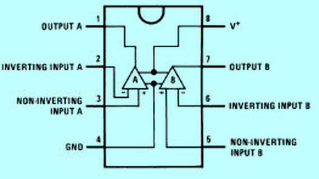
The LM358DR integrated circuit has a pin diagram of 8 pins.
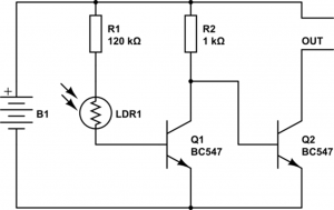
This dark sensor IC LM358 circuit puts a photodiode, a light-dependent resistor, and a phototransistor through their paces by simulating a low-light environment. To have the same effect, however, you will need to replace the photodiode and the phototransistor in place of the LDR. The circuit for a dark sensor that uses an LDR and an LM358 IC is depicted in the following schematic in graphical form. To put up the next circuit, you will need a light-dependent resistor (LDR), an integrated circuit with the part number LM358, a 9-volt battery, R2-1K, resistors R1-330R, and R3-10K, as well as a variable resistor with the part number VR1-10K, and a transistor with the part number Q1-C547.
The description that follows includes a dark sensor’s short circuit. If the light is kept from falling over the light-dependent resistor, the LM358 integrated circuit will start lighting the LED as soon as possible.
The instant functionality is achieved by substituting a photodiode for the LDR component of the circuit. Adjusting the sensitivity of the circuit requires you to make adjustments to the variable resistor by the amount of light that is present in the room.
The device begins functioning instantly when a phototransistor is used in place of a light-dependent resistor (LDR). Adjusting the sensitivity of the circuit requires you to make adjustments to the variable resistor in accordance with the amount of light that is present in the room.
The following circuit is a shock alarm circuit that may be utilized everywhere, from homes to cars. This circuit’s most typical application is in the form of an alarm system for use in anti-theft devices installed in motor vehicles. A piezoelectric sensor is utilized in this circuit to act as the shock sensor. This sensor must be attached to the door you are responsible for protecting. In this configuration, the LM358 serves as an inverted Schmitt trigger. The port1 of the device allows for the threshold voltage of the circuit to be adjusted. The function of feedback resistor R1 is handled by resistor R1.
If the piezo sensor is not triggered, then the sensor’s open-circuit voltage (o/p) will be very low. The Schmitt trigger is activated whenever the piezo sensor is tripped, which causes the open-collector output of the sensor to rise to a high level. After that, a buzzer sound is produced. Even when the vibration is removed, the sound of the buzzer can occasionally be heard to resemble a beeping sound. Because when the inverting input is increased, it has less of an effect when the LM358 integrated circuit is active, and the state cannot be easily reversed.
This article discusses the op-amp LM358, the operation of the IC LM358, and the various applications it has. We hope that this article has helped you gain a better understanding of the LM358 IC. In addition, if you have any questions concerning this or other op amp projects, please provide feedback in the form of comments in the below section.
For any IC you are planning to buy, we at ICRFQ supply them in bulk all over the world. Contact us today and we will sell you the best quality at an affordable price.
WhatsApp us