
Last Updated on October 22, 2023 by Kevin Chen
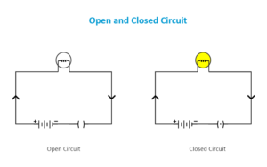
Open and closed circuit diagram. Source EdrawMax
Open and closed circuits. What do they mean and why should I know about them?
Just as the name suggests, the difference is based on the possibility of electric current to flow or not to flow.
An open current will allow the current to flow. A closed circuit, on the other hand will not allow the current to pass through.
Keep in mind that a complete circuit has a source and load. The current flow from the source to the load.
Would you like to know more about the differences between the two? Keep reading as we get into deep details of open circuit vs closed circuit.
What is a closed circuit
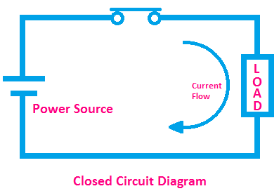
Closed circuit diagram source: EtechnoG
As the name suggests, the paths in this circuit is closed to allow the electric current to flow through.
It is a type of electric circuit in which the electric current is allowed to freely flow from the power source, through the various circuits and back to the components.
There is nothing along the path that interrupts the flow of the current.
Let’s take the example of a flashlight that is powered by a battery. The current will flow from the battery(power source) go through the bulb(flashlight) and back to the battery.
Any interruption across the path will leave it open hence the flashlight will go off.
In a closed circuit, the current undergoes a complete path.
Various components can be placed across the circuit paths. They include resistors, capacitors, transistors, ICs transformers among others.
Some electric components can multiply the current, others can boost. For example, a resistor will try to inhibit the current flow while a transformer will step up or down.
The current will flow continuously throughout the circuit until it is stopped either manually or automatically.
How do Identify a closed circuit?
Now that you know what a closed circuit is, how can I physically identify one?
This one easy. Probably you know what a conductor is. Well, you can identify this circuit by a conductive material that has created a loop. It is through this loop that the electric current flow through.
The loop should be unbroken so that no current can leak out or escape. Additionally, the circuit should have a couple of components connected to it or to one another.
Top examples of closed circuits
The examples of these circuits include:
-Home security systems: A typical home security system is a perfect example of a closed circuit. And this encompasses the wiring system that supplies current to all the components, devices and appliances at home.
-Automated manufacturing: When it comes to the manufacturing industries, machines always remain in close circuit. This is because most of them tend to run in a certain sequence and this can only be possible with a closed circuit.
-Security systems: There are various types of security systems some have lights while others have sound alarms. They are designed to react in case they detect threats. For such systems to work efficiently, they should remain closed.
Advantages of closed circuits
The main benefits of closed circuits include:
-Guarantee power delivery: Closed circuits ensure that the right amount of power is supplied to various devices and gadgets. They are the core to the proper functioning of these gadgets and devices.
-Minimize resistance: A circuit that remains closed means that there is minimal resistance to the flow of current, unless you have installed resistors.
-Enhanced security: From the examples, it is clear that closed circuits are good at monitoring and enhancing security. They ensure that nobody gains access to unauthorized sites.
-Cost-efficient: These circuits are easy to install and maintain. The fact that a good number of them are automated means you will not have to be physically available to open and close the circuit.
-Improved reliability: The make and design of closed circuits ensure that they are super reliable at all give conditions. They can withstand harsh conditions such as heat, water and humidity.
-High flexibility: Close circuits give room for more actions on the circuits. This is in the context that they allow you to introduce more components to the circuits without the need for modification.
-Reduced Risk interference: The fact that these circuits are closed means that they minimize the risk of interference from the external sources. These sources can be electromagnetic waves or even the radio frequency interference.
Disadvantages of closed circuits
The cons of closed circuits include:
-High cost: The cost of installing closed circuit devices can be considerably high. However, you can maneuver around this by buying from affordable suppliers and manufacturers.
-Limited coverage: Using a closed circuit system in some applications can limit you to specific geographical locations.
As you can see, you can get around most of these disadvantages by having an expert help you with the selection of devices and doing the right installation.
What is open circuit?
An open circuit is a complete opposite of the closed circuit. This one is open hence does not allow electric current to flow through.
You can compare it to a road or path that has a huge barrier or even a hole along it. You will not proceed with the journey until that path is closed.
The same analogy applies to an open circuit. While all the components are intact, there is a gap or disconnection that has been created and it prevents the loop from being complete.
An open circuit can be created intentionally or unintentionally. You will intentionally create this circuit when you switch it off. On the other hand, incidences that interfere with the cables and wires can result in accidental open circuits.
Damaged electronic components or even devices can also result to open circuits. For example, if a major component of a bulb is damaged, there will be an incomplete flow of current hence open circuit.
How can I tell that the circuit is open?
First, by physically checking out the circuit to find out if it has any broken points. This will require that you keenly observe throughout the loop. The task can be quite hectic if the circuit is large or complex.
An alternative and probably the most ideal method is by using a multimeter to test different points of the circuit. The multimeter will test the resistance and if it is near the infinity, then the circuit is open.
Here is a sample of an open circuit diagram
Examples of open circuits
Some ideal examples of open circuits include:
- An open switch of any electric circuit.
- A broken switch of a electric circuits
- A resistor that has a broken wire
- A capacitor with a broken wire
- A battery power source with a broken terminal
- A bulb that has a broken filament
- A disconnected plug
What are the dangers of unintentionally open circuits?
The most probable risk of unintentional open circuit is it could be an indication of a possible electrical failure. Probably a component in the circuit is damaged and needs urgent attention.
Otherwise, the circuit should always remain closed for it to work as desired by the users.
Comparing Open circuit vs closed circuits
Now that you know what these two types of circuits are, let’s do an in-depth comparison.
-Basic definition: As we have already defined an open circuit makes an incomplete path for the flow of electric current. On the other hand, a closed circuit makes up a complete path for the flow of electric current. In both cases, the current is supposed to flow from the source to the load and back.
-Flow of current: There is no flow of current in an open circuit. On the other hand, there is a complete flow of electric current in a closed circuit. Remember that this current flow from positive terminal to the negative terminal.
-Potential difference: Also known as voltage, this is the electrical energy difference between two points in an electric circuit. There is o potential difference between two terminals of an open circuit. On the other hand, there exists a voltage or pd difference at the terminals of a closed circuit.
-State of the circuit: An open circuit is in an ‘Off’ state while a closed circuit is always in an ‘On’ state.
-Basic symbol: The basic symbol of an open circuit is ( ) while the basic symbol of a closed circuit is ( . )
Conclusion
Now you know the clear differences between open circuit and closed circuits. Whenever you are handling electric and engineering projects, you should always be keen to spot the differences. This is a basic measure for all the technical tasks involving electricity.
And when it comes to connecting their components, ensure that they are correctly connected. If a component in the circuit is damaged, get the right replacement in good time.
Otherwise, we at ICRFQ are a reputable supplier of electronic components for circuits. Contact us and we will deliver.
If you want to find more Electronic Components Distributors, please check out the following articles:
Electronic Components Distributors In the USA
Electronic Components Distributors In UK
Electronic Components Distributors In China
Electronic Components Distributors In India
Electronic Components Distributors In Singapore
Electronic Components Distributors In Malaysia
Electronic Components Distributors In Vietnam
Electronic Components Distributors In South Korea
- Where to buy IC chips? The Best Guide? - March 26, 2024
- Breaking Down Barriers: Overcoming Obstacles in Cross-Border Electronic Component Trade - March 4, 2024
- Everything You Need to Know About Amplifier IC Chips - March 4, 2024


