
Last Updated on October 22, 2023 by Kevin Chen
A proportional-integral-derivative (PID) controller is an essential tool in the world of electronics. It helps you respond quickly to changes in output and input (loop feedback), which is essential when building complex machinery or sensitive devices. Such a control system is used in measuring various parameters including temperature, speed, and flow among many others.
This helps maintain constant output to changes in input. What is PID Controller? And Why Do You Need This? In this guide, we are going to do a complete breakdown of everything you should know about PID controllers.
What is a PID Controller?
A PID controller an instrument or simply a controller that helps you maintain the desired output (or output values) by measuring the difference between the desired value and current output.
In other words, it is a regulation tool used for regulating various variables in different environments. The variables can be speed,
It does this by making small changes to its input (or control) which is usually a variable, in an attempt to bring the error to zero.
PID controller is widely used in various industries such as aerospace, military, and transportation among many others.
What is PID?
Proportional, integral, and derivative are mathematical operations that help determine how much an action affects a result. The three components of PID are:
- Proportional (P)
- Integral (I)
- Derivative (D)
The proportional component determines how much the output should change based on the error or difference between the setpoint and actual output.
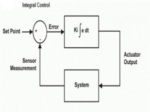
The integral component determines how much error to accumulate over time in order to increase or decrease the correction action, which can help eliminate steady-state errors and improve the accuracy and stability of control action over time.
The derivative component helps determine how quickly to respond to changes in error, which ensures that the controller responds quickly enough to achieve a desired level of performance but not so fast as to cause undesired effects due to overshoot or oscillation.
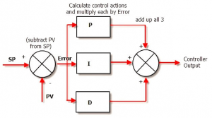
PID controller structure and block
As the name suggests, the structure of a typical PID controller comprises three control systems. These are proportional, integral, and derivative. These three components work together to generate an output that is used to control, manage, manipulate and regulate the operations of a system.
A PID block is designed to transfer the output direct to the process block.
A process block on the other hand comprises various electronic components such as actuators, controllers, valves among others. The feedback block compares the input signal with the reference signal, which is also known as a setpoint. From the comparison, it will generate the signal error that will be fed into a PID algorithm.
However, it is worth noting that not all the PID controllers have three components. Some controllers have just two of the variables, either PD or PI. The structure and design of the controller will depend on the specifications of the application area.
PID controller working principle
Now that we have discussed the design and structure of a typical PID controller, let’s now have a look at how it works.
The operation or working principle is straightforward; tuning the proportional, derivative, and integral terms.
The output signal is precisely proportional to the input, and this is true for both the proportional and derivative terms. However, the integral term is not as exact. It uses a sliding window function to approximate this step of the PID controller. This window function is smooth and continuous, but it also oscillates over time due to noise in your system or changes in temperature.
This means that there will always be some error in the output signal when integrating over time, even when using high-quality components such as military-grade sensors.
The PID controller compensates for this error by multiplying the output signal with a constant value (usually 1) before integrating over time. The resulting product of these two terms results in zero error when integrating over time, which means that we have reached our final reference point and no more tuning will be required for our PID controller to reach zero error at all times.
The working principle of a PID controller is divided into three distinct stages: proportional tuning, integral tuning, and derivative tuning. Let’s have a look at what happens at each stage.
Proportional tuning
This stage entails the adjustment and correction of the desired signal so that it is proportional; to the current error signal. Remember that the error signal is defined as the value difference between the setpoint and actual value. The PID controller is performing its job by adjusting the proportional gain so that it is always in the range of zero to one (or more) and so that this error signal exactly equals the error signal.
At this point, we are now controlling the output signal, which is proportional to the current error signal. This means that if we multiply the output signal with a constant value (usually 1), we will be able to control the output signal in such a way that it will always be proportional to our error signal. The resulting output will be an actual value of zero.
The PID controller can also perform this job by multiplying both sides of equation (1) with a constant value (usually 1). This is called Proportional tuning and is usually done for quick adjustment or for a very small deviation from our setpoint.
Integral tuning
This stage entails adjusting and correcting the desired signal so that it is proportional; to both its current errors as well as its past errors. It is usually done by adding a constant to the error signal.
The integral tuning is designed to generate output signals that are likely to interfere with the physical parameters. From the name, the tuning integrates the error signal with respect to time until you can achieve the minimum error.
Derivative tuning
This stage entails adjusting and correcting the desired signal so that it is proportional; to both its current errors as well as its past errors.
The derivative tuning involves adding a constant to the error signal. It is designed to generate output signals which will be resistant to future changes in the error signal.
The PID controller uses two parameters, called “gain” and “tune”. The gain parameter is responsible for determining how much of a change will be applied by the controller to the error signal. The tuning parameter is responsible for determining how far past the setpoint (current value) will be corrected by the controller.
Features of PID controller
PID controllers can be differentiated from other control methods such as on-off (bang-bang) control, proportional-integral (PI) controllers, and proportional-integral-derivative (PID) controllers based on their specific characteristics as listed below:
– A PID controller is an optimal control method that is capable of achieving the desired output with minimum overshoot and oscillation.
– A PID controller is a feedforward control method that uses the past and present states of a process to determine its future state.
– A PID controller uses three separate error signals (proportional, integral, and derivative) in order to calculate the appropriate amount of change in output.
– A PID controller can be implemented using either analog or digital circuitry.
– A PID controller is capable of achieving continuous tuning. Here, the controller output is adjusted while the process is operating in order to minimize any error between the actual and desired output.
– A PID controller has a low cost of implementation. Cheaper than some of the industrial control instruments on the market.
– A PID controller has relatively few tuning parameters that must be determined through trial and error.
– A PID controller is capable of achieving a wide range of responses.
– A PID controller is capable of achieving a large change in output for a small change in the input signal.
History of PID controller
To give you a better overview of the PID controller, let’s have a brief overview of its history. The first major development of the PID controller took place in 1911 and was developed by Elmer Sperry. The Sperry-type controller was the first controller to be capable of tuning continuously. It was developed by Elmer Sperry as a method of fine-tuning the speed of a machine.
The second major development was in 1923 and was developed by Corliss Lamont. This PID controller was the first to use proportional gain feedback control.
In 1947, Kramer and Korteweg published a paper on a model that would become one of the most popular PID controllers ever created. This paper proposed the use of an integrator in order to achieve proportional gain feedback control.
In 1974, Lax et al published another paper on a new type of linear regulator based on integral feedback. It is known as the Lax-Kramer-Korteweg (LKK) regulator. This type of regulator has been used extensively in industrial applications since then.
As expected, the PID controllers have been undergoing continuous improvements over the years. The latest developments have been in the area of adaptive controllers and neural networks.
Modern PID controllers feature sophisticated designs and components for better performance. The scope of their application has also expanded significantly. This simply means that they have been embraced in more industries.
PID controller design
An elaborate design process has to be followed and adhered to the fullest when designing a PID controller.
The design of a PID controller involves analysis and simulation of the process being controlled. The process is then modeled in the form of a mathematical model.
The model is then used to determine the operating conditions for the controller. After this, appropriate parameters are set for each component and element of the design.
After that, the controller is designed with all these elements in mind.
PID controllers are typically designed using Matlab or Simulink toolboxes. The MATLAB toolbox has an extensive library of models that can be adapted to various processes in a very short time. This makes it easy to understand how different models work and how to modify them for new applications
PID controllers can also be designed using other software such as Simulink or Control Engineering Toolbox (CET)
PID controllers are typically characterized by their output response, dynamic behavior, stability characteristics, minimum operating point and power consumption, etc. These characteristics help designers decide on the best PID controller for a given application.
The design process also has to factor in the physical constraints of the process, such as the size and weight of the controller and its components. This is vital because the smaller the controller, the easier it is to mount it on a robot or other machine.
The PID controller design is completed by checking the response of the model with different input and output values under varying conditions.
The PID controller design process usually takes around two hours to complete.
In summary, the PID controller design process entails the following steps:
Step 1: Detailed understanding of the application and process
Step 2: Designing the PID controller
Step 3: Testing the PID controller
Step 4: Finalizing the PID controller design
PID controller tuning
PID tuning is a process that involves maintaining a stable output by adjusting control parameters to reduce oscillations and stabilize output. In this process, a controller is used to maintain output at a target value.
The controller is adjusted so that it continually maintains the target value. If a change in input results in an undesired response, then the control system seeks to minimize these changes. This can be accomplished by modifying one or more of its parameters (input, output, etc.).
Here are the steps followed in PID controller tuning:
Step 1: Identifying the output of the controller
The whole process starts with finding the output of the controller. The output is measured with a digital or analog meter, which is then graphed.
Step 2: Identify the process input and target value
The next step is to identify the process input and desired target value. These values are used to determine which setpoint to use as a starting point for tuning.
Step 3: Finding the PID parameters
Now that we have identified the process input and target value, we need to find out the PID parameters required for its control. The PID parameters are measured in terms of control loop bandwidth, gain, etc., depending on the control algorithm used in designing it. A detailed discussion on how these parameters are calculated is provided in our blog article “PID Tuning of a Simulated Ventilation System”.
Step 4: Establishing an initial reference point
Once we have determined our PID parameters, we can establish an initial reference point (usually zero). This will be used as an anchor while tuning the PID parameters.
Step 5: Tuning the PID parameters
The next step is to tune the PID parameters. The tuning process starts with finding out the first derivative of the process input with respect to time. This is usually done by differentiating in a lookup table (LUT).
Once we have found this first derivative, we can then fine-tune our PID parameters in order to achieve zero error when integrating over this period. When this is achieved, we set our final reference point to zero and check for any oscillation in the output signal.
Step 6: Final reference point and final tuning
Once we have reached a final reference point, all that is left is to fine-tune our PID parameters in order to achieve zero error when integrating over the control period. This is usually done by setting a new reference point and repeating steps 4-6 until all errors are eliminated or until all LUT entries are exhausted.
Step 7: Permanently store your new settings
Once the PID parameters are tuned, the final step is to save these new settings into your build. After this, you will have a working PID controller that can be used in many different projects.
Types of PID controllers
We can classify PID controllers into different categories mainly on the basis of the type of control that has been used. The most common types that you are likely to find in the market include; an ON/OFF controller, a proportional controller, and a standard type controller.
What is the difference between these types? Let’s have a brief look at each of them.
ON/OFF controller
This is the simplest type o PID controller on the market. It has only one input and one output. The output is either ON or OFF. The controller basically performs the act of switching a device On and Off.
The most common application area of this type of PID controller is in the limit controller which uses a latch relay system. It can change its output signal depending on the parameters or values at the setpoint.
Proportional controller
This type of PID controller is designed to overcome the cycling problem that is usually experienced on the On/Off controller. It works on the principle of comparing the setpoint with the actual value and then changing it to a new value.
The advantage of this type of controller is that it can be used in any application environment where there is a need for a stable output signal. It can be used in many different applications including machine control and robotics.
Standard type controller
This type of PID controller is widely used in industrial applications. It has two inputs and two outputs. The output signal is proportional to the input signals as per a given formula. This helps to overcome the problem of noise, which usually affects the operation of an On/Off controller. These controllers are very reliable, and they do not require any external components apart from a power supply source to work properly. This type of controller is ideal for applications like automatic load balancing, temperature control, fluid flow management, etc.
Applications of PID controllers
Where are PID controllers used? Given their top-of-range performance and high-end features, it is obvious that PID controllers are used in an array of industrial applications.
The controllers are used for controlling various variables such as temperature, pressure, and fluid flow, among others. Here are some common applications of PID controllers;
-Temperature control in industries: Most manufacturing and processing activities require regulation of temperature. These processes often involve the production of different types of products, and hence the temperature of various parts must be regulated. PID controllers work with heat sensors and fans to facilitate heat management.
-Intelligent load balancing: In industrial applications, it is necessary to have the ability to control the flow of power over several devices. This allows you to achieve maximum efficiency and minimize the amount of energy consumed. PID controllers are used for this purpose.
-Fluid flow management: In industries such as oil refineries and chemical plants, it is necessary to manage fluid flow so that it does not mix with other substances or contaminate any equipment or machinery inside them. PID controllers are used for this purpose because they can control fluid flow at the desired rate without causing any damage or contamination.
-Automation: In areas such as the manufacturing industry and medical facilities, it is necessary to automate a lot of processes so that things can be done in an efficient manner. PID controllers are used for this purpose because they can control processes with precision and accuracy.
-Regulate humidity: In areas such as the pharmaceutical industry, it is necessary to regulate humidity levels so that they do not exceed a certain limit. PID controllers are used for this purpose because they can regulate humidity at a precise rate without causing damage to any equipment or machinery in the room.
Advantages and disadvantages of PID controller
Now let’s look at the pros and cons of using PID controllers.
Advantages
-These controllers are process independent. They do not depend on any particular process to operate.
-Are strong and durable. They do not require frequent maintenance
-Do not require any external power source.
-Do not require any special training to operate.
-Are very accurate in their control output.
-Fast response makes the devices that have them respond fast to different variables.
Disadvantages
-Can be unstable, especially when they are not designed and tuned to the highest precision.
-Frequent tuning can lead to fast wear and tear of the controller components.
-Can be very difficult to troubleshoot especially if it develops unfamiliar complications.
Conclusion
We have discussed all the essentials of PID controllers. What next? You will now be able to choose the best PID controller for your application. Of course, you have to choose a reliable and reputable manufacturer who will deliver the controller.
On the side note, we at ICRFQ can connect you to such companies. As a sourcing agent, we have contacts of PID controller manufacturers in China.
If you want to find more Electronic Components Distributors, please check out the following articles:
Electronic Components Distributors In the USA
Electronic Components Distributors In UK
Electronic Components Distributors In China
Electronic Components Distributors In India
Electronic Components Distributors In Singapore
Electronic Components Distributors In Malaysia
Electronic Components Distributors In Vietnam
Electronic Components Distributors In South Korea
- Where to buy IC chips? The Best Guide? - March 26, 2024
- Breaking Down Barriers: Overcoming Obstacles in Cross-Border Electronic Component Trade - March 4, 2024
- Everything You Need to Know About Amplifier IC Chips - March 4, 2024


