
Last Updated on October 22, 2023 by Kevin Chen
Because measuring the high voltages and currents involved with power transmission and distribution networks is difficult, instrument transformers are frequently employed to scale these values down to a more manageable level. This is because measuring meters or instruments and protective relays are low-voltage devices that cannot be directly linked to a high-voltage circuit for system measurement and protection.
These transformers isolate the measuring or protective circuit from the primary circuit, which operates at high power levels and lowers voltage and current levels.
Current transformers lower the current level to the instrument or relay’s functioning range, whereas potential transformers convert a high voltage to a low voltage circuit. This essay will go over the potential transformers in great detail.
What Is a Potential Transformer?
A voltage step-down transformer decreases the voltage of a high voltage circuit to a lower level for measurement purposes. These are linked to the line to be monitored, either across or parallel.
This transformer works on the same basic principle as a regular power transformer and is built similarly. The abbreviation PT is commonly used to refer to potential transformers.
The primary winding is made up of many turns connected across the high-voltage side or line where measurements or protection are required. The secondary winding, which is connected to voltmeters, potential coils of wattmeters and energy meters, relays, and other control devices, has a smaller number of turns. Potential transformers can be either single-phase or three-phase. These are designed to provide a secondary output voltage of 110 V, regardless of the primary voltage rating.
Due to the high impedance of voltmeters and potential coils on other meters, only a modest current flows through the secondary of PT. As a result, PT behaves like a standard two-winding transformer with no load. The VA ratings of PTs are modest, ranging from 50 to 200 VA, because of the minimal load (or burden) on the PT. One end of the secondary side is attached to the ground for safety purposes.
Potential Transformer Working Principle
Between the ground and the phase is linked the potential transformer connected to the power network whose voltage should be detected. The high voltage network is connected to the primary section of a potential transformer, and the second section is connected to a multimeter. The two sides are magnetically connected and work based on electromagnetic induction due to mutual induction.
A voltmeter is used to detect the reduced voltage on the secondary side compared to the voltage in the primary section. The minimal current passes over the secondary side due to the high impedance in the system, and it works similarly to a typical transformer with no or low power. As a result, these transformers operate in a voltage range of 50 to 200VA.
Based on the convention transformer, the transformation ratio is
V2=V1×N1N2
Where ‘V1’ is the primary winding voltage, ‘V2’ is the secondary side voltage, ‘N1’ is the primary section number of turns, and ‘N2’ is the second section number of turns. The above formula can be used to determine a network’s high voltage.
Circuit Diagram
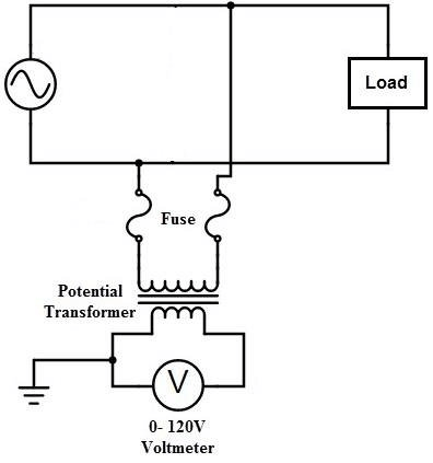
The primary winding of the potential transformer has more twists than the secondary section, which has fewer turns. The central part is exposed to a high input AC voltage (connected to the high voltage network to sense). A voltmeter can measure the lower output voltage on the secondary side. The two windings are magnetically connected, but there is no physical connection between them.
High-quality potential transformers are designed to operate at low magnetic current, low flux density, and low load. It uses great conductors and an iron center compared to a traditional variety. It can be built in both a shell and a core configuration to reach the utmost precision. Core-type potential transformers most commonly transport high voltage to lesser outputs.
It employs co-axial sections to decrease the leakage reactance. As the potential types are performed at high voltages, the significant voltage primary section is divided into small parts coils/turns to reduce the insulation cost and problems. The phase shift between the output and input voltage should be controlled accurately to keep the lower voltage by changing the load. Windings layered with vanish cambric and cotton tape to decrease the insulation price.
Covering the coils with complex fiber separators is done. The high voltage outputs (over 7kV) are also sent to the primary lines through oil-filled bushings. A potential transformer’s natural part has many turns, whereas the second section has fewer. To detect the reduced output voltage, a voltmeter or multimeter is utilized.
Construction of Potential Transformer
The magnetizing current is minimal because the potential transformer has a high-quality core that operates at a low flux density. The transformer’s terminal should be constructed with the least amount of voltage ratio variation with load and the minor phase shift between the input and output voltage.
The primary winding has a lot of turns, while the secondary winding has a few. The co-axial winding is utilized in the potential transformer to reduce the leakage reactance. By separating the primary winding into parts and reducing the insulation between the layers, the insulation cost is also lowered.
Connection of Potential Transformer
The potential transformer is linked to the circuit in parallel. The potential transformer’s primary windings are connected directly to the power circuit whose voltage is monitored. The potential transformer’s secondary terminals are attached to a piece of measurement equipment such as a voltmeter or wattmeter. The magnetic circuit of the primary windings magnetically couples the secondary windings of the potential transformer.
The transformer’s primary terminal is rated for 400V to a few thousand volts, whereas the second terminal is rated for 400V. The transformation ratio, also known as the turn ratio, is the ratio of the primary voltage to the secondary voltage.
Types of Voltage Or Potential Transformers
Outdoor and indoor potential transformers are the most common classifications.
Outdoor Potential Transformers
These can be single or three-phase voltage transformers with various operating voltages for outside relaying and metering applications. These electromagnetic single and three-phase voltage transformers have a voltage range of up to 33KV. Outdoor potential transformers for single-phase voltages above 33 kV can be of two types: electromagnetic and capacitive voltage transformers (CVT).
Electromagnetic or Wound Type Conventional Potential Transformer
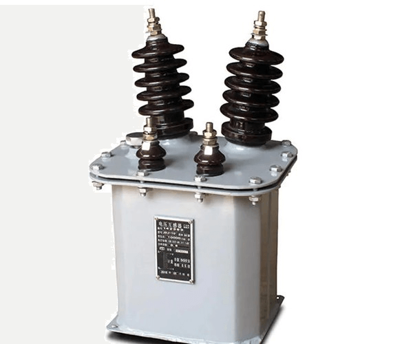
These transformers are comparable to oil-filled wire wound transformers. The electromagnetic kind of PT, in which the tap tank is linked to the line terminal, is depicted below. The tank has a plug for filling the oil, and it is set on insulator support.
A ground terminal and an oil drain plug are supplied at the base. Primary is connected between the two phases or between one phase and ground in this configuration. So, at the top, one end of the primary is connected to the mainline, and at the bottom, the other end is brought out and grounded with other ground terminals.
Secondary connections, including an earth terminal, are positioned at the bottom of the terminal box and are connected to the metering and relay circuits. Due to insulation concerns, these are only used up to or below 132 KV operational voltages.
Capacitive Voltage Transformers (CVTs)
It’s a capacitive potential divider connected to the main line’s phase and ground. It could be a coupling capacitor or a CVT with bushing. These two varieties are electrically comparable to one another, but the difference is in the capacitance formation, which determines their rated load (or load).
A coupling capacitor comprises a series of oil-impregnated paper and aluminum foil capacitors that are connected in series. Primary and secondary terminals are connected across the capacitors to achieve the primary and secondary voltages desired.
Condenser-type bushings with tapping are used in the bushing type CVT. CVTs are also more cost-effective when utilized for power line carrier communication.
Indoor Potential Transformers
These are also available as molded, magnetic single or three-phase PTs. There are two types of mounting mechanisms: fixed and drawout. This form of PT insulates all primary winding components to the rated insulation capacity from the earth. These are intended for the high-precision operation of relays, measuring instruments, and other control equipment in indoor service.
PT or voltage transformers are divided into two types based on their function: metering voltage transformers and protection voltage transformers.
Errors in Voltage Transformer
The voltage produced in the secondary winding of an ideal voltage transformer is an exact percentage of the primary voltage and is in phase opposition. However, due to voltage decreases in primary and secondary resistance and the power factor of the burden on secondary, this is not the case in genuine Pts. Voltage transformers suffer from ratio and phase angle mistakes due to this.
Conclusion
Because the potential windings of the protective instrument are not directly linked to the network in the case of high voltage, potential transformers are primarily used in the protecting relaying system. As a result, both lowering the input voltage and isolating the protective system from the principal network are required.
Lastly at ICRFQ, we manufacture the best electrical components in China. Any time you have a question or are planning to purchase any component for your electrical connectivity, contact us.
If you want to find more Electronic Components Distributors, please check out the following articles:
Electronic Components Distributors In the USA
Electronic Components Distributors In UK
Electronic Components Distributors In China
Electronic Components Distributors In India
Electronic Components Distributors In Singapore
Electronic Components Distributors In Malaysia
Electronic Components Distributors In Vietnam
Electronic Components Distributors In South Korea
- Where to buy IC chips? The Best Guide? - March 26, 2024
- Breaking Down Barriers: Overcoming Obstacles in Cross-Border Electronic Component Trade - March 4, 2024
- Everything You Need to Know About Amplifier IC Chips - March 4, 2024


