
- Audio Products
- Battery Products
- Boxes, Enclosures, Racks
- Cable Assemblies
- Cables, Wires
- Cables, Wires – Management
- Capacitors
- Circuit Protection
- Computers, Office – Components, Accessories
- Connectors, Interconnects
- Crystals and Oscillators
- Crystals, Oscillators, Resonators
- Discrete Semiconductor
- Embedded Computers
- Fans, Thermal Management
- Filters
- Hardware, Fasteners, Accessories
- Inductors, Coils, Chokes
- Industrial Controls, Meters
- Integrated Circuits (ICs)
- Isolators
- Kits
- Line Protection, Distribution, Backups
- Magnetics – Transformer, Inductor Components
- Maker/DIY, Educational
- Memory Cards, Modules
- Motors, Solenoids, Driver Boards/Modules
- Networking Solutions
- Optical Inspection Equipment
- Optoelectronics
- Potentiometers, Variable Resistors
- Power Supplies – Board Mount
- Power Supplies – External/Internal (Off-Board)
- Programmers, Development Systems
- Prototyping Products
- Relays
- Resistors
- RF/IF and RFID
- Sensors, Transducers
- Soldering, Desoldering, Rework Products
- Static Control, ESD, Clean Room Products
- Switches
- Tapes, Adhesives
- Test and Measurement
- Tools
- Transformers
- Uncategorized
The Complete Guide to Electronic Components
Electronic devices have become an indispensable element of our daily life. They have improved the comfort and convenience of our lives. Electronic devices have a wide range of applications in the modern world, from aviation to medical and healthcare industries. The electronics and computer revolutions are inextricably linked.
The majority of gadgets contain small electronic circuits that control machines and handle data. Electronic circuits, to put it another way, are the lifeblood of numerous electrical gadgets. This article goes over the many types of electrical components and how they work in electronic circuits.
In this post, we’ll go through the various sorts of electronic components in greater detail. We’ll go through the composition, how it works, and the component’s function and relevance for each type.
Electronic Components
Creating electronic circuits, particularly ICs and PCBs, has been automated thanks to today’s technology. Depending on the circuit’s intricacy, the number and placement of components may change. It is, nevertheless, constructed with a limited number of standard components.
Electronic circuits are made up of the components listed below
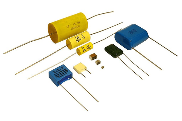
1. Capacitor
Capacitors are commonly employed in electronic circuits of various types. A capacitor is an electrical component with two terminals that may store energy electrostatically in an electric field. It functions as a miniature rechargeable battery that stores electricity, to put it simply. It can charge and discharge in a fraction of a second, unlike a battery.
Capacitors exist in a variety of sizes and designs, but they all share the same basic components. A dielectric or insulator layered between two electrical conductors or plates separates them. Plates are made of conductive materials like thin metal sheets or aluminum foil. On the other hand, a dielectric is a non-conducting material like glass, ceramic, plastic film, air, paper, or mica that does not conduct electricity. The two electrical connections protruding from the plates can be used to connect the capacitor to a circuit.
How Do capacitors Work?
An electric field occurs across the insulator when you supply voltage to the two plates or link them to a source, causing one plate to build a positive charge while the other accumulates a negative charge. Even when disconnected from the source, the capacitor maintains its charge. The stored energy will flow from the capacitor to the load as soon as you connect it to a power source.
The quantity of energy held in a capacitor is known as capacitance. The capacitance of a device determines how much energy it can store. Moving the plates closer together or increasing their size will increase the capacitance. You can also improve the capacitance by improving the insulating properties.
Function and Significance of capacitors
Despite their appearance, capacitors can serve a variety of purposes in a circuit, like blocking direct current while allowing alternating current to pass or smoothing the output of a power source. They’re also utilized to keep voltage and power flow stable in electric power transmission systems. Power factor adjustment is one of the most important roles of a capacitor in an AC system; without it, single-phase motors would not have enough starting torque.
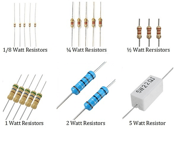
2. Resistor
A resistor is an electrical device with two terminals that oppose current flow. In an electronic circuit, it’s arguably the most basic component. Because resistance is included in practically all electronic circuits, it is also one of the most frequent components. Color-coding is common.
How does the Doe resistor work?
A resistor may appear to be insignificant. It may appear like it does nothing but consume energy. It does, however, serve an important purpose: it regulates the voltage and current in your circuit. Resistors, in other terms, allow you control over the layout of your circuit.
When an electric current is applied to a wire, all of the electrons begin to move in the same direction. It’s the same as water running through a pipe. Because there is less room for water to go through a thin pipe, less water will flow through it.
When current travels through a small wire in a resistor, the electrons find it increasingly difficult to wiggle through it. In other words, as the length and thinness of the wire grow, the quantity of electrons flowing through the resistor decreases.
Function and Significance of a resistor
The three most typical applications for resistors are regulating current flow, splitting voltage, and resistor-capacitor networks.
· Limiting the Flow of Current
Current will flow at dangerously high levels if resistors are not added to a circuit. It has the potential to overheat and damage other components. An LED, for example, might be connected directly to a battery and still function. However, after a while, the LED will become as hot as a fireball. Because LEDs are less heat tolerant, they will eventually burn.
However, adding a resistor to the circuit will reduce the current flow to an optimal amount. As a result, you can leave the LED on for longer without it overheating.
· Dividing Voltage
To lower the voltage to the required level, resistors are also utilized. A specific component in a circuit, such as a microcontroller, may require a lower voltage than the circuit as a whole. A resistor is used in this situation.
Assume a 12V battery powers your circuit; the microcontroller, on the other hand, simply requires a 6V supply. To divide the voltage in half, simply connect two resistors with the same resistance value in series. The cable connecting the two resistors has cut the circuit’s voltage, where the microcontroller can be connected in half. You can lower the voltage in the circuit to any level by using appropriate resistors.
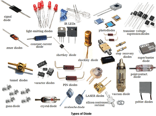
3. Diode
A diode is a two-terminal device that enables just one direction of electric current to pass. As a result, it functions similarly to a check valve or a one-way street in the electronic world. It’s a device that converts an Alternating Current (AC) to a Direct Current (DC) (DC). A semiconductor material (semiconductor diode) or a vacuum tube is used to make it (vacuum tube diode). The majority of diodes nowadays, however, are constructed of semiconductor materials, mainly silicon.
Vacuum diodes and semiconductor diodes are the two types of diodes that exist. A vacuum diode is made up of two electrodes (cathode and anode) inside a vacuum glass tube that is sealed. There are p-type and n-type semiconductors in a semiconductor diode. A p-n junction diode is what it’s called as a result. Silicon is commonly used; however, Germanium or selenium can also be used.
How Do diodes Work?
· Vacuum Diode
When a filament heats the cathode, an unseen cloud of electrons known as space charge accumulates in the vacuum. Although electrons are emitted from the cathode, they are repelled by the negative space charge. No current passes via the circuit because electrons cannot reach the anode. The space charge dissipates when the anode is made positive. Current begins to flow from the cathode to the anode as a result. Note, electric current travels only from the cathode to the anode and never from the anode to the cathode within the diode.
· P-N Junction Diode
A p-n junction diode is made up of p-type and n-type silicon semiconductors. Boron is commonly doped into p-type semiconductors, resulting in holes (positive charge). On the other hand, an n-type semiconductor is doped with antimony, which adds a few additional electrons (negative charge) to it. As a result, an electric current can pass between the two semiconductors.
When p-type and n-type blocks are combined, the electrons of the n-additional type merge with the p-holes types to generate a depletion zone with no free electrons or holes. To put it another way, current cannot travel through the diode.
When the battery’s negative terminal is connected to n-type silicon, and the positive terminal is connected to p-type silicon (forward-bias), the current begins to flow because electrons and holes can now pass across the junction. No current flows through the diode if the terminals are reversed (reverse-bias) since holes and electrons are pushed apart from each other, enlarging the depletion zone. A junction diode, like a vacuum diode, can only allow current to flow in one direction.
Function and Significance
Despite being one of the most basic components in an electrical circuit, diodes have a wide range of uses in a variety of sectors.
· AC to DC Conversion
The most common and essential application of a diode is the conversion of alternating current (AC) to direct current (DC). A half-wave (single diode) or full-wave (four diodes) rectifier is typically used to convert AC power to DC power, particularly in residential power supplies. When an alternating current power supply is passed through a diode, only half of the alternating current waveform is passed through it. Because this voltage pulse is utilized to charge the capacitor, it generates constant and continuous DC currents with no ripples. Different diode and capacitor combinations are also used to construct various voltage multipliers, multiplying a modest AC voltage into high DC outputs.
· Bypass Diodes
Solar panels are frequently protected by bypass diodes. Overheating occurs when the current from the other cells passes through a broken or dirty solar cell. As a result, the overall output power falls, resulting in hot areas. To protect the solar cells from overheating, the diodes are connected in parallel. This straightforward setup controls the voltage across the faulty solar cell while enabling current to flow through intact cells to the external circuit.
· Voltage Spike Protection
Most inductive loads create a high voltage when the power supply is abruptly stopped. This sudden voltage increase may cause damage to the loads. However, by attaching a diode across the inductive loads, you can protect expensive equipment. These diodes are called by a variety of names, including snubber diode, flyback diode, suppression diode, and freewheeling diode, depending on the type of security.
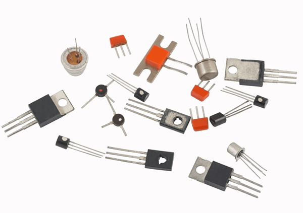
4. Transistor
Transistors, being one of the most important components of an electronic circuit, have transformed the area of electronics. These tiny three-terminal semiconductor devices have been available for more than five decades. They are frequently employed as amplifiers and switching devices. They can be thought of as relays without moving parts because they can turn something ‘on’ or ‘off’ without any movement.
Initially, Germanium was employed to make extremely temperature-sensitive transistors. Today, however, they are built of Silicon, a semiconductor substance found in the sand, because Silicon transistors are far more temperature-tolerant and less expensive to produce. Bipolar Junction Transistors (BJT) are classified into two types: NPN and PNP. Each transistor has three pins: base (b), collector (c), and emitter (e) (e). The layers of semiconductor material utilized to construct the transistor are referred to as NPN and PNP.
How Does transistor Work?
An NPN transistor is created by sandwiching a p-type silicon slab between two n-type bars. The emitter is connected to one of the n-types, while the collector is connected to the other. The p-type is connected to the base. Surplus holes in p-type silicon operate as barriers, preventing current passage. When a positive voltage is applied to the base and collector and a negative voltage is applied to the emitter, electrons begin to flow from the emitter to the collector.
In a PNP transistor, the arrangement and quantity of p-type and n-type blocks remain inverted. One n-type transistor is placed between two p-type blocks in this sort of transistor. Because voltage allocation differs, a PNP transistor operates differently. A positive voltage is required for the base of an NPN transistor, whereas a negative voltage is required for the base of a PNP transistor. To put it simply, the current must flow away from the base for a PNP transistor to turn on.
Function and Significance of transistors
In most electronic circuits, transistors serve as both switches and amplifiers. Designers frequently use a transistor as a switch because, unlike a basic switch, it can convert a little current into a much larger one. While a simple switch can be used in a simple circuit, an advanced circuit may require changing quantities of current at different stages.
· Transistors in Hearing Aids
The hearing aid is one of the most well-known applications of transistors. A small microphone usually picks up the sound waves in the hearing aid, which is then converted into fluctuating electrical pulses or currents. These currents are magnified when they pass through a transistor. The amplified pulses are then sent through a speaker, where they are converted back into sound waves. As a result, you might hear a much louder version of the ambient sounds.
· Transistors in Computers and Calculators
We all know that computers use the binary language of “zero” and “one” to store and process data. However, most people are unaware that transistors play a crucial part in the creation of logic gates, which are the backbones of computer programs. Transistors are frequently used with logic gates to create a unique configuration known as a flip-flop. Even after the base current is removed from this setup, the transistor stays “on.” When a new current passes through it, it now turns on or off. As a result, a transistor may hold a zero when it’s turned off or a one when it’s turned on, which is how computers work.
· Darlington Transistors
Two PNP or NPN polar junction transistors are combined to form a Darlington transistor. It bears the name of its creator, Sidney Darlington. A Darlington transistor’s main purpose is to deliver a large current gain from a low base current. These transistors can be found in power regulators, display drivers, motor controllers, light and touch sensors, alarm systems, and audio amplifiers, among other instruments that require a high current gain at a low frequency.
· IGBT and MOSFET Transistors
Insulated-Gate Bipolar Transistor (IGBT) transistors are commonly employed as amplifiers and switches in a variety of instruments such as electric cars, trains, refrigerators, air conditioners, and even stereo systems. Metal-Oxide-Semiconductor Field-Effect Transistors (MOSFETs) are commonly employed in integrated circuits to manage a device’s power levels or to store data.
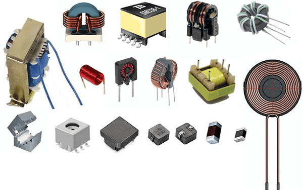
5. Inductor
An inductor, sometimes known as a reactor, is a two-terminal passive component of a circuit. This gadget stores energy in its magnetic field, which it then returns to the circuit as needed. The magnetic field formed by the first inductor influences the second inductor when two inductors are arranged side by side without touching. The invention of the first transformers was made possible by a pivotal discovery.
It’s the most basic component, consisting only of a coil of copper wire. The inductance of a coil is related to its number of turns. The coil is sometimes twisted around a ferromagnetic material such as iron, laminated iron, or powdered iron to improve inductance. The form of the core can also increase the inductance of this core. Toroidal (donut-shaped) cores provide superior inductance to solenoidal (rod-shaped) cores for the same number of turns. Because it is difficult to connect inductors in an integrated circuit, resistors are frequently used instead.
How Does inductor Work?
A magnetic field is created whenever current travels across a wire. The inductor’s peculiar design, on the other hand, results in a much greater magnetic field. This strong magnetic field, in turn, repels alternating current while allowing direct current to pass through. This magnetic field can also be used to store energy.
Consider a basic circuit with a battery, a switch, and a light bulb. When you turn the switch on, the bulb will begin to glow brilliantly. To this circuit, add an inductor. The light goes from brilliant to dim as soon as you flip the switch on. On the other hand, when the switch is turned off, it glows incredibly bright for a fraction of a second before turning off altogether.
When you flip the switch on, the inductor begins to form a magnetic field with the electricity, briefly limiting the current flow. When the magnetic field is complete, however, only DC travels through the inductor. That’s why the light in the bulb dims and brightens.
The inductor retains some electrical energy in the form of a magnetic field throughout this time. When you turn off the switch, the magnetic field maintains a constant current in the coil. As a result, the bulb shines brightly for a short time before going off.
Function and Significance inductor
Inductors are useful, but their size makes them difficult to incorporate into electronic circuits. They add a lot of weight and take up a lot of space because they are bulkier than other components. As a result, resistors are commonly used to replace them in integrated circuits (ICs).
Inductors, on the other hand, have a wide range of industrial applications.
· Filters in Tuned Circuits
Inductors are used to select the desired frequency in tuned circuits, which is one of its most prevalent applications. They’re commonly used to make filters with capacitors and resistors in parallel or series. An inductor’s impedance rises as the frequency of the signal rises. As a result, a single inductor can only function as a low-pass filter. You may make a notched filter by combining it with a capacitor since the impedance of a capacitor lowers as the frequency of the signal increases. As a result, various combinations of capacitors, inductors, and resistors may be used to make various sorts of filters. They can be found in a wide range of electrical devices, including televisions and desktop computers.
· Proximity Sensors with Inductors
The majority of proximity sensors operate on the inductance principle. An inductor or coil, an oscillator, a detecting circuit, and an output circuit are the four components of an inductive proximity sensor. The oscillator generates a fluctuating magnetic field. Eddy currents begin to build up whenever an object comes close to this magnetic field, lowering the sensor’s magnetic field.
The detecting circuit determines the sensor’s strength, and the output circuit triggers the appropriate response. Contactless proximity sensors, also known as inductive proximity sensors, are prized for their dependability. They are utilized as parking sensors in automobiles and trucks and at traffic lights to measure traffic density.
· Induction Motors
The most typical application of inductors is an induction motor. Induction motor inductors are usually mounted in a permanent position. In other words, they are not permitted to align with the magnetic field in the vicinity. The shaft is rotated by a revolving magnetic field created by an AC power supply. The rotational speed is controlled by the power input. As a result, induction motors are frequently employed in fixed-speed applications. Induction motors are extremely reliable and durable because there is no direct contact between the motor and the rotor.
· Transformers
The introduction of inductors led to the development of transformers, which are one of the most important components of power transmission networks. Combining the inductors of a shared magnetic field can be used to make a transformer. They’re typically used to adjust the voltage of electrical lines to the correct amount.
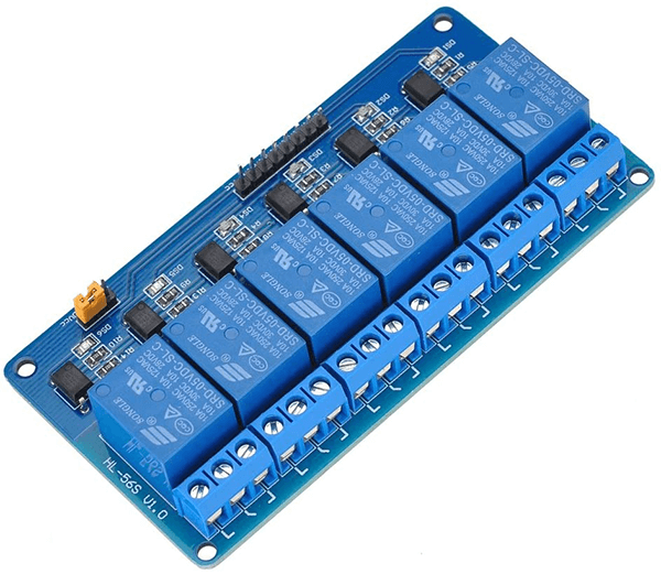
6. Relay
A relay is an electromagnetic switch that may both electromechanically and electronically open and close circuits. To operate a relay, you only need a small amount of current. They’re usually utilized in control circuits to regulate low currents. Relays can, however, be used to manage strong electric currents. A relay is an electronic version of a lever. You can turn it on with a low current to turn on (or leverage) a larger current circuit. Electromechanical and solid-state relays are the two types of relays.
A-frame, coil, armature, spring, and contacts make up an electromechanical relay (EMR). The frame supports the relay’s numerous components. The armature is the portion of a relay switch that moves. The armature is moved by a magnetic field generated by a coil (usually copper wire) coiled around a metal rod. The conducting elements that open and close the circuit are known as contacts.
An input circuit, a control circuit, and an output circuit make up a Solid-State Relay (SSR). An electromechanical relay’s input circuit is analogous to a coil. The control circuit links the input and output circuits, while the output circuit functions similarly to an EMR’s contacts. Solid-state relays are becoming more widespread because they are less expensive, faster, and more dependable than electromechanical relays.
How Does relay Work?
It’s either a Normally Closed (NC) or a Normally Opened (NO) relay, whether you’re utilizing an electromechanical or solid-state relay. When there is no power supply, the contacts of an NC relay stay closed. When there is no power source, however, the contacts of a NO relay stay open. In a nutshell, whenever the current passes through a relay, the contacts open or close.
The relay coil of an EMR is energized by the power source, which creates a magnetic field. The magnetic coil attracts a ferrous plate positioned on the armature. When the current is turned off, spring action returns the armature to its resting position. A single or numerous contact might be included in a single EMR package. A circuit is called a Single Break (SB) circuit if it just has one contact. On the other hand, a Double Break Circuit (DB) has two contacts. Single break relays are typically used to control low-power devices like indicator lamps, while double break contacts are typically used to operate high-power devices like solenoids.
When operating an SSR, you must apply a voltage greater than the relay’s specified pickup voltage to activate the input circuit. To deactivate the input circuit, apply a voltage less than the relay’s specified minimum dropout voltage. The signal is transferred from the input circuit to the output circuit by the control circuit. The output circuit turns on the load or does the desired activity.
Function and Significance relay
Most control methods employ relays as key protection and switching devices because they can control a high current circuit with a low current signal. They are also capable of detecting faults and anomalies in power distribution systems. Typical applications include, among others, telephones, vehicles, traffic control systems, home appliances, and computers.
· Protective Relays
If any anomalies are identified, protective relays trip or isolate the circuit. When a fault is discovered, they can sometimes trigger alarms. The function of a protective relay determines its type. An overcurrent relay, for example, is designed to detect currents that exceed a predetermined value. When such a current is measured, the relay activates, tripping a circuit breaker to protect the equipment from damage.
A distance relay or impedance relay, on the other hand, can detect irregularities in the current/voltage ratio rather than monitoring their amplitude separately. When the V/I ratio falls below a certain threshold, it swarms into action. Protective relays are typically used to protect equipment such as motors, generators, and transformers.
· Automatic Reclosing Relay
An automatic reclosing relay is intended to produce multiple reopening circuit breakers that a protective relay has already tripped. For example, if there is a significant voltage decrease, your home’s electrical circuit may experience multiple temporary power outages. These outages occur as a result of a reclosing relay attempting to activate the protective relay automatically. If it is successful, the electricity will be restored. Otherwise, there will be a total blackout.
· Thermal Relays
A thermal relay operates on the thermal effect of electrical energy. In a nutshell, it can detect changes in ambient temperature and turn on or off a circuit accordingly. It is made comprised of a bimetallic strip that heats when an overcurrent travel across it. The heated strip bends and shuts the No contact, causing the circuit breaker to trip. The most typical use of a thermal relay is to safeguard an electric motor against overload.
7. Quartz Crystal
Quartz crystals are used in a variety of applications in the electronics sector. They are, however, usually utilized as resonators in electronic circuits. Quartz is a kind of silicon that occurs naturally.
To fulfill the increased demand, it is currently created synthetically. It has a piezoelectric action. When you apply physical pressure to one side of the crystal, the ensuing vibrations generate an alternating current voltage across the crystal. Quartz crystal resonators are available in a variety of sizes depending on the purpose.
Quartz crystals are either created synthetically or found naturally. They are frequently employed in the fabrication of crystal oscillators, which generate an electrical signal with a precise frequency. Quartz crystals are typically hexagonal, with pyramids at the ends. They are, however, chopped into rectangular slabs for practical purposes. The most frequent cutting formats are X cut, Y cut, and AT cut. This slab is sandwiched between two metal plates known as holding plates. A quartz crystal or crystal oscillator’s exterior shape can be cylindrical, rectangular, or square.
How Does It Work?
When an alternating voltage is applied to a crystal, mechanical vibrations occur. The resonance frequency of these vibrations or oscillations is determined by the cut and size of the quartz crystal. As a result, it generates a continuous signal. Quartz oscillators are inexpensive and simple to synthesize. They are available at a variety of frequencies ranging from a few kHz to a few MHz. Crystal oscillators are impressively stable in terms of time and temperature because they have a higher quality factor or Q factor.
Function and Significance of quartz crystals
Quartz crystals and resonant elements can be used in oscillators and filters in electronic circuits because of the extremely high Q factor. This very reliable component can be found in radio frequency applications, oscillator clock circuits in microprocessor boards, and digital watches as a timing element.
· Quartz Watches
Traditional coil spring watches have the drawback of having to wound the coil regularly. Pendulum watches, on the other hand, rely on the gravitational pull. As a result of differences in gravitational pull, they tell time differently at different sea levels and elevations. Quartz watches, on the other hand, are unaffected by any of these circumstances. Quartz timepieces are powered by batteries. A small quartz crystal usually controls the gears that govern the second, minute, and hour hands. Quartz watches consume extremely little energy; thus, the battery can survive for a long time.
· Filters
Quartz crystals can also be used as filters in electronic circuits. In radios and microcontrollers, they’re frequently employed to filter out undesirable signals. A single quartz crystal is used in the majority of simple filters. Advanced filters, on the other hand, may contain many crystals to meet performance requirements. These quartz crystal filters outperform those made with LC components by a long shot.
Conclusion
Electronic gadgets affect practically every area of our life, from chatting with loved ones across countries to brewing a hot cup of coffee. What, however, causes these electronic devices to complete seemingly time-consuming activities in a matter of minutes? All electronic equipment is built on the foundation of tiny electronic circuits. Understanding the purpose and Significance of the various components of an electronic circuit can be learned by reading about them.
Lastly, if you are a retailer, electronic gadgets manufacturer or planning to venture into any of them, ICRFQ is your one-stop distributor of electronic gadgets contact us today.
SEND A RFQ TODAY
- Where to buy IC chips? The Best Guide? - March 26, 2024
- Breaking Down Barriers: Overcoming Obstacles in Cross-Border Electronic Component Trade - March 4, 2024
- Everything You Need to Know About Amplifier IC Chips - March 4, 2024