
Last Updated on October 22, 2023 by Kevin Chen
Any digital electrical circuit will mostly contain pull-up & pull-down resistors if you look it over. When there is no input condition, they are employed to properly bias digital gates’ inputs to prevent them from floating around arbitrarily. Pull-up and pull-down resistors use input and output signals for any microcontroller in an embedded system like an Arduino to communicate with external hardware devices and the General-Purpose Input Output (GPIO). You may reach either “high” or “low” states in the circuit by incorporating the pull-up & pull-down resistors. If you don’t implement it, your software will read a “floating” impedance state and leave your GPIO pins unconnected.
Pull-Up Resistors
The inclusion of a pull-up resistor creates a second loop over the crucial parts while ensuring that the voltage is well-defined even while the switch is open. It is employed to guarantee that a wire is pulled to a high logical level in the absence of an input signal. It is not a unique variety of resistors.
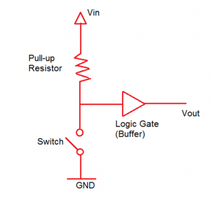
Without a driving signal, they function as straightforward fixed-value resistors connected between the voltage supply and the proper pin to determine the input or output voltage. Whenever the switch is activated, the gate input voltage is drawn up to the input voltage level. The gate’s input voltage is immediately grounded when the switch is closed. You must apply a pull-up resistor when you want to draw the signal to the “high” position and have a low default impedance condition.
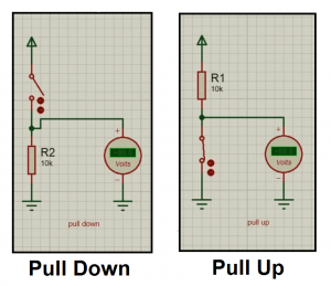
The voltage supply and a specific pin of the digital logic circuit were connected in the diagram above using a pull-up resistor with a fixed value. When the switch is open, the pull-up resistor and switch work together to adjust the voltage between the ground and VCC actively. The state of the circuit won’t be impacted at the same time.
A short circuit will occur if a pull-up resistor is not used. Shorting the pin directly to either ground or VCC will eventually cause circuit damage. According to Ohm’s law, if there is a pull-up resistance, a tiny amount of current will pass from the source to the resistors and the switch before reaching the ground.
Pull-Down Resistors
Pull-down resistors come in handy when turning circuits on and off. For instance, a push-button and a pull-down resistor can be used to turn the course on and off. It will make it possible for current to pass through it under specific pressure or for certain buttons to be pressed.
Pull-down resistors function with a minimal level of resistance that permits current to travel through them and, when required, activate switches. The series resistance is recommended to calculate Ohm’s Law while employing pull-down resistors appropriately. Only pull-down resistors with positive polarity will work, and we must connect them to the powering circuit. If this occurs, the circuit will cut off the current since it cannot pass through the resistor.
Several components are turned on at once when a switch is flipped on. As a result, a current will simultaneously flow across all of these parts. A positive voltage gradually develops across each of them. Due to its restriction on current flow, the resistor prevents this.
As a result, there is no possibility of a negative voltage across it. As a result, the resistor will shut off the circuit at any negative voltage. What we want is not what is happening here.
Pull-down resistors cannot be used with numerous buttons. Because the current won’t pass through them, they won’t be able to perform their intended purpose. A pull-down resistor can be used to restrict current from flowing through a switch that is turned off for extended periods. It entirely shuts down as a result of it.
Methods for Determining the Actual Values of Pull-Down Resistors
Using Ohm’s Law to determine the power in a circuit, we may determine the actual value of a pull-down resistor’s resistance. We’ll refer to the voltage logic as Low. The pull-down resistor’s controllable current, Resource, comes from the device. It will have a minimal voltage drop across it, VL(max).
R pull-down = (VL(max) – 0) / Isource
This calculation can be changed depending on whether the resistor is positioned in front of or behind the load device.
Through the resistor, there will be a significant quantity of electricity flowing. The voltage drops across it could therefore be rather substantial. As a result, we must carefully select this number to avoid causing harm to the circuit or any of its components.
It is also possible to combine the pull-up & pull-down resistors into a single unit that simultaneously accomplishes both functions. Bidirectional resistors are what we call them. As a result, depending on how we use them, they can perform both roles since they permit current to flow through them in either direction.
Pull-down transistors benefit from being useful in one or more circuits, which is one of their advantages. They are small and don’t have to be connected parallel to the circuit. The pull-down transistor, which accepts voltages from 2.5V to 5V, can also be helpful with resistors greater than its equivalents. Pull-down transistors are also useful for managing circuits with lower power requirements. The pull-down resistor’s sensitivity will determine how much current flows through them. Additionally, pull-down transistors can speed up circuits’ on/off switching. It is helpful in circumstances like control panels.
Pull-up vs Pull-down Resistor: What Are The Different
A pull-up resistor differs slightly from a pull-down resistor. Only positive polarities are utilized with pull-up resistors. Both positive and negative polarity pull-down resistors are capable of operation.
The distinction is that a resistor will experience a voltage drop when a current pass through it. Pull-up resistors assist in “pulling up” the input signal’s voltage to the required level. This enables us to operate the circuit with less energy. Pull-down resistors, however, are useful for lowering voltages. They won’t harm linked devices or cause them to operate incorrectly because they are not excessively high.
When utilizing pull-down resistors, we must be aware that a significant voltage drop across it due to a high input current may harm some devices or even push them above their design limitations. It is usually recommended to utilize a pull-up resistor for circuit demands when an input voltage is higher than 5 V because these won’t harm the device. When employing voltages over this, issues develop, which we address by using series-connected resistors.
Then-current is only temporarily passed when pull-down resistors and transistors are used to control the state of logic circuits. So, unlike other resistors, the current won’t flow as long. Therefore, this must be considered when calculating how much electricity to consume. Their non-damaging nature is their key benefit over pull-up resistors alone. Additionally, they don’t need safeguards against overheating or excessive voltage increases.
Frequency Characteristics
The line range is 50% for the pull-up power frequency response and 25% for the pull-down power frequency response. However, a pull-down circuit’s frequency response may be larger than 50% due to the capacitance between the input and output. As a result, we advise ensuring the input and output capacitances are as low as feasible.
High and Low Level
The pull-up resistor’s output ranges from 0.8 to 2 volts. The pull-down circuit’s high input level exceeds its low output level by a factor of 1.5. Finally, 3 V to 15 V is the high output level. However, it is limited to 30V. Therefore, for a pull-down resistor with a 50-ohm input impedance, the threshold level of pull-down signal current is 0.5A.
Driving Capability And Power Consumption
The pull-up resistor’s maximum output signal must be at least 20 mW. In contrast, a pull-down circuit’s full input signal must be 10 W. When employing a transistor output buffer, the resistance needed to drive the pull-down signal logic should be less than 50. A pull-up resistor uses between 3 and 5W of electricity, while a pull-down circuit uses less than 1W.
Applications
In addition to being utilized as discrete components, we combine pull-up & pull-down resistors with building bidirectional circuits. These circuits function by allowing an input current to pass through the resistor due to a biasing mechanism. Whether or not it outputs the voltage will depend on whether this is above or below a specific level.
For instance, they come in handy in various logic gates, such as the half adder, which uses logic 1 to allow current flow through the transistor. As a result, the resistor experiences a voltage drop, which activates the circuit’s power source. The use of tri-state buffers is another illustration. Pull-up resistors are present on only one of the buffer sides, leaving the other side without any. As a result, there won’t be any power loss, and the current will only flow to the load when logic 0 is present. This circuit is utilized during data transmission between devices to prevent data loss by holding off on applying power until it is required.
Utilizing pull-up and pull-down resistors has several drawbacks, but their inefficiency is their principal drawback. It will therefore produce heat instead of work by converting some energy. They may also experience significant voltage drops if you do not take the proper measures, damage, or improper operation of connected equipment.
We may construct a modified version of this circuit without requiring extra parts. It gives the gadget an interface with an input voltage already there.
What Parts of A Computer Are This Compatible With?
Power supplies and debugging are both possible uses for this. For instance, when connecting your computer to a pull-down resistor-using device, the switch will either be turned on/off depending on whether the positive or negative ground is utilized. As a result, it’s not a good idea to use both positive and negative grounds at once when using a pull-down resistor.
Conclusion
Pull-up and pull-down resistors have the benefit of requiring the least power to operate all the methods. It qualifies them for low-power designs. They also don’t need extra buffers or other components to function together because they can produce their voltage. Diodes and transistors are just a few solutions that can be used when low power is required. Even so, they might not offer a resistor’s level of efficiency. It would decrease the overall effectiveness of a circuit created using this technique.
However, since these circuits might be the most suitable for some applications, there might not be a choice. It would therefore be best if you took into account their overall cost-effectiveness.
For more details regarding pull-up vs pull down resistors or any other electrical component, contact us at ICRFQ. We manufacture the best electrical components in China.
If you want to find more Electronic Components Distributors, please check out the following articles:
Electronic Components Distributors In the USA
Electronic Components Distributors In UK
Electronic Components Distributors In China
Electronic Components Distributors In India
Electronic Components Distributors In Singapore
Electronic Components Distributors In Malaysia
Electronic Components Distributors In Vietnam
Electronic Components Distributors In South Korea
- Where to buy IC chips? The Best Guide? - March 26, 2024
- Breaking Down Barriers: Overcoming Obstacles in Cross-Border Electronic Component Trade - March 4, 2024
- Everything You Need to Know About Amplifier IC Chips - March 4, 2024


