
Last Updated on October 22, 2023 by Kevin Chen
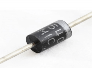
Diodes are a type of semiconductor device that is commonly employed. A rectifier diode is a two-lead semiconductor that only allows current to flow in one direction. In most cases, a P-N junction diode is created by combining n-type and p-type semiconductor materials.
The anode is the P-type side, whereas the cathode is the n-type side. Diodes come in various shapes and sizes and are employed in multiple applications. Rectifier diodes convert AC to DC voltage and are essential in power systems. The Zener diodes are used in circuits to regulate voltage and prevent undesired changes in DC sources.
What Is A Rectifier?
A rectifier is a device that converts two-way alternating current (AC) into single-directional direct current (DC) (DC). Rectifiers come in various physical shapes and sizes, ranging from vacuum tube diodes and crystal radio receivers to modern silicon-based systems.
Half-wave rectifiers are the simplest rectifiers. They work by taking out one side of the AC and only allowing one current direction to pass through. Half-wave rectifiers are inefficient converters because half of the AC power input is wasted. A full-wave rectifier, which employs both sides of the AC waveform, is a more efficient conversion option.
What Is A Diode?
A diode is a one-way current switch made of semiconductors. It allows the current to move in one direction while restricting it. Because they convert alternating current (ac) to pulsing direct current (dc), diodes are also known as rectifiers (dc). The type, voltage, and current capability of diodes are all rated.
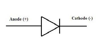
The polarity of a diode is determined by the anode (positive lead) and cathode (negative lead) (negative charge). Most diodes enable the current to pass when the anode is given a positive voltage.
What is a Rectifier Diode?
A rectifier diode is a semiconductor diode used in the rectifier bridge application to convert AC (alternating current) to DC (direct current). Using a rectifier diode with a Schottky barrier in digital electronics is highly prized. This diode can handle currents ranging from a few mA to a few kA and voltages up to a few kV.
Silicon can be used to design rectifier diodes, and they are capable of carrying large amounts of electric current. Although these diodes are not well-known, they are still made of Ge or gallium arsenide. Ge diodes have a lower permissible reversed voltage and a lower permissible junction temperature. The Ge diode has a lower threshold voltage value than Si diodes while working in forwarding bias.
There are two technical parameters in a rectifier diode: allowable limit and characteristic parameters. The arrowhead points in the direction of typical current flow in the symbol of a rectifier diode illustrated below.
Rectifier Diode Circuit Working
A p-n junction is created by combining n-type and p-type materials with a specific fabrication procedure. This P-N junction is referred to as a “DIODE” since it has two terminals that might be referred to as electrodes (Di-ode).
When an external DC supply voltage is provided to an electronic device via its terminals, biasing occurs.
Unbiased Rectifier Diode
When no voltage is applied to a rectifier diode, it is an unbiased diode. The N-side will have a majority of electrons and extremely few holes (due to thermal excitation), while the P-side will have a majority of charge carriers holes and very few electrons.
In this process, free electrons from the N-side diffuse (spread) into the P-side and recombine in holes, leaving +ve stationery (not movable) ions on the N-side and -ve immobile ions on the P-side of the diode.
The immobility on the n-type side at the junction edge. The stationary ions near the junction edge on the p-type side act similarly. As a result, many positive and negative ions will collect near the junction. This newly developed zone is known as the depletion region.
A static electric field known as Barrier Potential is formed across the PN junction of the diode in this region. It prevents holes and electrons from migrating further across the junction.
Forward Biased Diode
The diode is in forwarding bias when the positive terminal of a voltage source is connected to the p-type side of a PN junction diode, and the negative terminal is attached to the n-type side. The electrons are resisted by the DC voltage supply’s negative terminal and drift towards the positive terminal.
Under the influence of applied voltage, electron drift causes current to flow in a semiconductor. This current is known as the “drift current.” Because electrons make up the majority of carriers in n-type, the current is called electron current. Because holes are the majority carriers in p-type, the DC supply’s positive terminal repels them, causing them to move across the junction to the negative terminal. As a result, in p-type, the current is the hole current.
The majority of carriers cause a Forward current, which flows from positive to negative of the battery and is the polar opposite of electron flow.
Reverse Biased Diode
Suppose the positive terminal of the source voltage is connected to the n-type end of the diode and the negative terminal is attached to the p-type end of the diode. In that case, there will be no current flowing through the diode except reverse saturation current. As the reverse-biased voltage increases, the junction’s depletion layer becomes broader.
Minority carriers cause a tiny current to pass from the n-type to the p-type end of the diode. Reverse Saturation Current is the name given to this current. In p-type and n-type semiconductors, minor carriers are mostly thermally produced electrons and holes.
The depletion layer will be destroyed when a particular value is achieved if the reverse applied voltage increases continuously, producing a high reverse current to flow through the diode. The diode may be permanently destroyed if this current is not externally limited and exceeds the safe value.
These fast-moving electrons clash with the device’s other atoms, knocking off extra electrons from them. The freed electrons release even more electrons from the atoms by dissolving the covalent connections. The outcome is a significant increase in current flow across the p-n junction, known as carrier multiplication. The occurrence is referred to as Avalanche Breakdown.
Half-Wave Rectifier
One of the most common applications for the diode is to convert AC electricity to DC power. Because a diode can only conduct current in one direction, there will be no current if the negative input signal. A half-wave rectifier is what this is called.
Full-Wave Rectifier
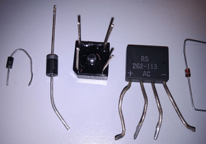
We may make both halves of the waves positive by using a full-wave rectifier diode circuit consisting of four diodes—a forward channel across the diode bridge for positive and negative input cycles.
The circuit is successfully removed since two of the diodes are forward biased and the other two are reverse biased. Full-wave rectification is achieved when both conduction routes cause current to flow in the same direction via the load resistor.
In power supplies, full-wave rectifiers are used to convert AC voltages to DC voltages. The ripple from the rectification process is reduced by connecting a big capacitor in parallel with the output load resistor.
Parameters
The rectifier diode is classified using the following limiting parameters.
- VF is the Forward voltage through determined IF forwarding current
- IR is The current in reverse at VRWM peak reverse voltage operation.
- IFN is The diodes max average current or rated current in the forward bias
- IFRM is the Peak, Repeatable current diode conduction
- IFSM is the Peak, non-repeatable current conduction
- VRWM is the Peak, Reverse Voltage Operation
- VRRM – Peak, Repetitive Reverse Voltage
- VRSM – Peak, Non-Repetitive Reverse Voltage
- PTOT – The whole value of the dissipated power on the electronic component
- Tj – Highest Temperature of Junction in Diode
- Rth – Thermal Resistance below Operating Conditions
Maximum Temperature
Different factors, such as the ambient temperature where the rectifier diode is working, can affect the various characteristics stated above. Heat is generated by all semiconductor devices, especially those utilized in power supplies. One of the most challenging issues is avoiding thermal runaway, which occurs when a diode’s temperature rises, causing the current to increase until the device is destroyed.
To avoid this, each diode parameter reference temperature, such as the reverse leakage current of Si diodes, is typically extracted at 25°C of ambient temperature. Still, it is nearly twice for every 10°C. As the temperature rises, the forward junction potential falls from 2 mV to 3 mV for every 1°C rise in temperature.
High Current
The rectifier diode with a double high current is the best example of a high-performance diode with a 2x 30A current.
STPS60SM200C is a double high voltage rectifier diode developed by STMicroelectronics. This diode can all benefit from the welders, base stations, AC/DC power supply, and industrial applications.
The VRRM has a 200V breakdown voltage, a 640mV conduction voltage, and a 2x30A current memory. An ESD, also known as electrostatic discharge, can provide additional protection up to 2kV. The operational temperature range of this diode is -40° C to 175° C. These values will allow the diodes to be used in the base stations under any conditions.
How to Test a Rectifier Diode?
The following procedures can be used to test the rectifier diode.
The basic multimeter is primarily used to determine the polarity of a rectifier diode, such as an anode or cathode. There are at least three ways to do this, but the two simplest are to use an Ohmmeter and the VDC measurement function.
Using Ohmmeter
The Ohmmeter will specify the diode’s anticipated forward voltage, which is roughly 0,7 in forward-bias mode. The Ohmmeter will read ‘1’” in reverse-bias mode, indicating exceptionally high resistance. Using a diode check function is the same as using the method described above.
VDC Measurement Function
According to a multimeter, the voltage drop for a silicon diode in forward bias is 0.7V. A multimeter is used in reverse bias to specify the estimated value of the whole Voltage Supply. Rectifier diodes are mostly employed in rectification, which is the process of converting an AC voltage to a DC voltage. They’re used in circuits where a large number of currents must pass through the diode.
The rectifier diodes are manufactured of Si and have a forward voltage drop of 0.7V. The 1N4001 diode is suitable for circuits with low voltage and a current of less than 1A.
The current flow is a diode’s characteristic; otherwise, the current does not supply based on the applied voltage direction. This converts AC voltage to DC voltage. The current supply connects the anode and cathode electrodes of this diode once the anode electrode is connected to the +ve terminal.
Applications
Rectifier diodes have a wide range of uses. Here are a few examples of typical diode applications:
- Isolating signals from a supply
- Rectifying a voltage, for example, converting AC voltages to DC voltages
- Signal size control
- Signal mixing
- Signal detection
- Lighting systems
- LASER diodes
As a result, a rectifier diode permits electrical current to flow in just one direction, used to operate the power supply. Compared to regular diodes, these diodes can handle the highest current flow. Normally, these diodes are used to convert alternating current (AC) to direct current (DC) (DC). These can be designed in the same way as discrete components or integrated circuits. These are made of Si and have a relatively large PN junction surface, resulting in high capacitance in reverse-bias circumstances. To increase the combination’s PIV (peak-inverse-voltage) rating, the two rectifier diodes are linked in series to high-voltage supply.
Conclusion
A rectifier diode is also known as a semiconductor diode is used to convert alternating current into direct current (usually at a low frequency of 50 Hz with a high amount of power emitted during the load).
The fundamental duty of this component, to “rectify” the meaning of the term, is to convert alternating current (AC) into direct current (DC) using rectifier bridges. The rectifier diode with the Schottky barrier in digital electronics is very valuable. Rectifier diodes can withstand currents up to a few kiloamperes and voltages up to a few kilovolts.
If you need rectifier diodes or other electrical components, contact us at ICRFQ. We manufacture the best electrical components in China.
If you want to find more Electronic Components Distributors, please check out the following articles:
Electronic Components Distributors In the USA
Electronic Components Distributors In UK
Electronic Components Distributors In China
Electronic Components Distributors In India
Electronic Components Distributors In Singapore
Electronic Components Distributors In Malaysia
Electronic Components Distributors In Vietnam
Electronic Components Distributors In South Korea
- Where to buy IC chips? The Best Guide? - March 26, 2024
- Breaking Down Barriers: Overcoming Obstacles in Cross-Border Electronic Component Trade - March 4, 2024
- Everything You Need to Know About Amplifier IC Chips - March 4, 2024


