
Last Updated on October 22, 2023 by Kevin Chen
The Braun tube was discovered in 1897, and Jonathan used it to sweep the trace in 1899, together with beam developing plates and magnetic field developing plates. Cathode ray tubes were often employed for calculations in laboratories during the early years of 1920, although they had weak cathode and vacuum emitter systems. Zworykin created a method of cathode ray tube sealing utilizing a thermionic emitter in 1931 to eliminate this problem. Because of this method, General Radio was able to develop an oscilloscope that may be used elsewhere as well. Oscilloscopes were so designed in this manner. The workings of the sampling oscilloscope, sampling methods, and applications are all clearly explained in this article.
What is a Sampling Oscilloscope?
Understanding the fundamental operation of a typical oscilloscope is essential before discussing sampling oscilloscopes. A multimeter is a device that can be used to measure a single value for the voltage in circuits that have constant voltages. When you begin creating more complex circuits, this is no longer necessary. An oscilloscope is useful in this situation.
You may observe how voltage varies over time using an oscilloscope. The term “signals” refers to these voltages used to transmit information, including an audio signal that plays music on a speaker.
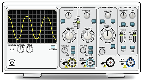
An oscilloscope’s display screen includes a graph that displays the measured voltage signal and other information. Time is shown by the horizontal axis, and voltage is represented by the vertical axis.
You may assess whether the behavior of your circuits is functioning correctly with this display. Additionally, it will enable you to find any issues with your circuits, such as noise or unexpected signals.
Sampling Oscilloscope
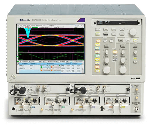
The sampling oscilloscope improves digital oscilloscopes, including some added functions for unique applications. This device employs the stroboscopic light approach to analyze quick electrical impulses as its underlying concept.
To make the entire image appear as a continuous signal on display, distinct samples from various signal regions are taken across uninterrupted cycles in this oscilloscope. In this case, a signal can be created using a thousand points, and it should be noted that the resulting signal can be boosted using an amplifier with a low bandwidth before being displayed on display.
The primary objective of this sampling oscilloscope is to detect the high-frequency waveform in the 50 GHz band. When using the slope’s sample rate in evaluation, a signal with a high frequency can be produced at the oscilloscope’s output.
Working of Sampling Oscilloscope
The sampling oscilloscope receives and reconstructs the input signal. During the occurrence of the sample pulses, the input signal voltage will be monitored at very brief intervals. The sample pulses will only activate the sampling circuit during the brief intervals. Only those voltage levels will be vertically positioned on the cathode ray tube’s screen.
The position of the spot will indicate the various signal amplitudes during the different sampling periods as the following samples are obtained over the following cycles of the input voltage. The increasing voltage will be simultaneously applied to the horizontal plates by the sample instants. As a result, a pattern is created on the C.R. tube screen, following the spot’s point-by-point movement.
The input terminals are wired up to the sampling gate. The input signal forward biases the gate’s diodes. As a result, the input terminals are provided with the gate input capacitance. As a result, the input voltage is applied to the gate input capacitor. The vertical amplifier amplifies this voltage before applying it to the vertical deflecting plates. The sampling pulse must give the sampling gate permission for this to happen. The sampling process is timed to the input signal. As a result, the vertical amplifier has a delay circuit. The input signal activates the sweep circuit.
The blocking oscillator begins a linear ramp voltage upon receiving the trigger pulse. This is sent to the comparator. The comparator evaluates the output of the staircase generator against the ramp voltage’s amplitude. The staircase voltage generator can move one step once the ramp voltage amplitude matches the staircase voltage amplitude. The sampling rate is now given a sampling pulse. The vertical amplifier only accepts the sample input at this precise moment. The vertical deflecting plates receive their application after being amplified.
Here it should be observed that the trigger pulses and the horizontal movement of the beam are coordinated. As previously said, the trigger pulses determine the sample instants. The size of the steps produced by the staircase generator determines the final image that appears on the C.R. tube’s screen. The image comprises a series of horizontal spots; the farther apart they are, the larger the step.
Sampling Method for Signal Tracing
Mixing the dots in the sampling procedure can create a full signal. Every dot in this is made up of a single, consecutive cycle of the signal, and the subsequent dots are each made up of a single successive cycle of the signal’s next-to-smallest cycle.
Sampling Oscilloscope Block Diagram and Explanation
Below is a block schematic of a sampling oscilloscope.
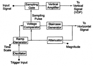
It is evident from the preceding figure that the sampling gate receives the input signal. When the sampling signal is applied to this sampling gate, it will open and sample the input signal. It is crucial that sampling can be coordinated using the input signal’s frequency.
The input signal is delayed when the vertical amplifier is employed in the circuit; once the signal has been amplified, the signal can then be sent to the vertical plates.
The oscillator will be activated through the trigger signals once the sampling cycle begins, allowing for the creation of a linear ramp output voltage. It is possible to provide the voltage comparator unit with the signal produced by the ramp generator.
In this instance, the staircase signal—generated by the staircase generator—is used to evaluate the ramp signal. The staircase is improved by one step during evaluation, allowing for generating a sampling pulse after the amplitudes of the two signals are equal. The sample gate will again be opened, and the cycle can be carried out similarly.
The output image resolution is determined by the steps-per-inch created by the staircase generator. There will be more samples once the steps dimension gets smaller. Consequently, the image resolution will be greater.
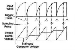
The waveforms for several blocks of the sampling oscilloscope are shown in the following image. The frequency samples in a sampling oscilloscope may be as low as a hundredth of the frequency of the i/p signal. As a result, the 1 GHz, 10 MHz amplifier BW input signal frequency is needed.
What Is Delayed Sweep In A Sampling Oscilloscope?
There are many oscilloscopes of lab quality that have a delayed-sweep capability. The instrument’s adaptability is increased by this function, which also makes it easy to analyze waveform jitter or rise time, verify pulse time modulation, and magnify a specific area of the undelayed sweep, among many other uses. With the help of the delayed sweep technique, you may precisely extend the interval between the trigger point and the start of the scope sweep.
The start of the delayed sweep can occur anywhere between a few microseconds and perhaps 10 seconds or more when the scope is utilized in the delayed-sweep mode. With the delayed sweep operation, the instrument operator can examine a brief waveform period, such as an oscillation or ringing that takes place during a short period of a lower-frequency waveform.
Using the delayed sweep feature, it is sometimes more convenient to trigger at a position other than the trailing or leading edge. However, in some circumstances, the delayed-sweep function is the only way to achieve a measurement. Consider the scenario when the measurement point on a waveform is too far away from the only trigger point to allow for a reliable display on a CRT screen. The issue can be resolved by employing a delayed sweep to trigger at the only accessible trigger point and then beginning the sweep at the place of interest.
Sampling Method
Before each sample cycle, the trigger pulse activates an oscillator, producing liner voltage. The staircase will move one step until the amplitudes of the two voltages are equal, at which point a sampling signal can be created to open the sampling gate designed to take a sample of the input voltage. The staircase generator’s step size significantly impacts the signal resolution. There are other sample-taking techniques, but the real-time sample and comparable sample methodology are typically utilized.
Real-Time Sample Method
This method uses a digitizer to list the top spots in a single sweep while operating fast. The primary goal of this is to record high-frequency transient occurrences accurately. The transient pulse is sufficiently distinct from its surrounding ones that the current or voltage level cannot be related at any given moment.
These acts don’t repeat themselves; hence they need to be listed in the same amount of time that they occur. The sample rate can be 100 samples/sec, and the sampling frequency can be as high as 500 MHz. To store a high-frequency signal, fast memory is required.
Equivalent Sample Method
This method relies on the estimate and prophesies principles, which are easily attained via cyclic signals. With this method, a digitizer obtains samples from numerous wave repeats. Therefore, it may utilize a single sample from each repeat or none. The frequency of the resulting signal is higher than the scope sampling rate. Thus, two techniques—Random & Sequential—can be used to perform this kind of sampling.
Random Method
The most used method for sampling is this one. This method primarily uses an internal clock that may be set to work with input signals and continuously takes trigger samples from the signal to trigger. The samples that were taken were randomly activated but were regular in time. Although independent of the triggering rate, this approach records samples at their typical time intervals.
Sequential Method
This technique triggers using samples. Once the trigger has been detected, a little delay can be used to record the sample. Verify the delay because it must be very brief yet clearly specified. The following trigger, when it occurs, is listed after a slight delay compared to the one before.
Microseconds to seconds make up the delayed sweep time range. For instance, if the delay is ‘t’ the first time, it will be higher than ‘t’ the following time. In this manner, samples are used repeatedly with an added delay until the time window is filled.
The technique utilized to extend the time between the starting and triggering locations of the scope sweep is known as the delayed sweep. It increases the oscilloscope device’s adaptability. A signal that is not delayed can be magnified through the delayed sweep oscilloscope. It is typically used in various applications to quantify the signal’s rise time or modulation of pulse time.
Advantages
The following are some benefits of sampling oscilloscopes.
● A device with reduced bandwidth is utilized to measure the highly high-speed signals.
● The sampling method is excellent for instantly converting the input signal into a signal with a lower frequency range.
● It can respond and store data in quick bit form.
Disadvantages
The following are some drawbacks of sampling oscilloscopes.
● This oscilloscope’s primary flaw is that it only can measure continuous waves.
● The sampling oscilloscope’s frequency range is mainly determined by how it is built.
Applications
The following are some uses for sampling oscilloscopes.
- Different electrical signals are employed in the sampling oscilloscope to see a high-speed signal on display.
- They are utilized to capture signals sent through a recorder.
- The signals are capable of precise measurement.
- Are Not only low frequency (a few kHz) signals used with this oscilloscope but also high frequency (hundred MHz) signals. With a signal repetition rate of 10 Hz or higher, it is possible to calculate each signal component up to 200 s after the set-off point.
Conclusion
This article will describe how the sampling oscilloscope was modified to work around the difficulties posed by BW requirements. These devices mostly show signals with a frequency higher than 300 MHz. Therefore, the excellent signal display is mainly achieved through the sampling technique. There are 1000 dots in this show. Every additional point in the following input cycle can be used to get the vertical deflection for each dot. The horizontal signal deflection can be achieved by sending the staircase signal in the direction of the horizontal deflecting plates.
For more details on Sampling Oscilloscope, contact us at ICRFQ. We manufacture quality and affordable electrical components in China.
If you want to find more Electronic Components Distributors, please check out the following articles:
Electronic Components Distributors In the USA
Electronic Components Distributors In UK
Electronic Components Distributors In China
Electronic Components Distributors In India
Electronic Components Distributors In Singapore
Electronic Components Distributors In Malaysia
Electronic Components Distributors In Vietnam
Electronic Components Distributors In South Korea
- Where to buy IC chips? The Best Guide? - March 26, 2024
- Breaking Down Barriers: Overcoming Obstacles in Cross-Border Electronic Component Trade - March 4, 2024
- Everything You Need to Know About Amplifier IC Chips - March 4, 2024


