
Last Updated on October 22, 2023 by Kevin Chen

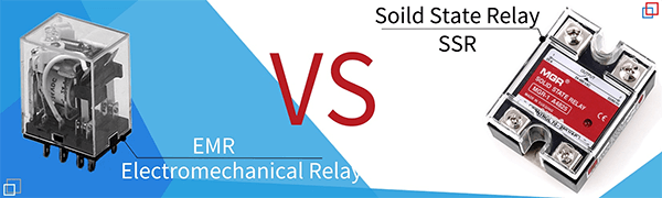
A mechanical relay is thought to be similar to a solid-state relay by everyone. However, because they both have control and load-switching circuits, these two devices have several distinctions. We’ll learn more about the differences and similarities in this article.
What Is A Relay?
A relay is a power switching device that allows you to distribute power without manually opening and closing switches. A relay only needs a minimal electrical signal to turn on and off the electricity. This signal functions as a symbolic “gatekeeper” for a much larger electrical signal. The capacity to manage a high-power signal with low power has made relays so popular throughout the history of electronics.
What Is A Solid-State Relay?
Unlike electromechanical relays (EMRs), which operate and switch a supply using coils, magnetic fields, springs, and mechanical contacts, the solid-state relay (SSR) has no moving parts. Instead, it uses solid-state semiconductors’ electrical and optical properties to perform input to output isolation and switching.
SSRs provide complete electrical isolation between their input and output contacts, just like a traditional electromechanical relay. Their output acts as a conventional electrical switch in that it has a very high, almost infinite resistance when nonconducting (open) and very low resistance when conducting (closed). Instead of the traditional mechanical normally-open (NO) contacts, solid-state relays can be configured to switch AC and DC currents by employing an SCR, TRIAC, or switching transistor output.
The main advantages of solid-state relays over traditional electromechanical relays are that they have no moving parts to wear out and thus no contact bounce issues. They can also switch both “ON” and “OFF” much faster than a mechanical relay’s armature can move, as well as zero voltage and zero current turn-on and turn-off, which eliminates electrical noise and transients.
Solid-state relays are available in various common off-the-shelf packages with output switching capabilities ranging from a few volts or amperes to several hundreds of volts and amperes. However, because of their power semiconductor and heat sinking requirements, solid-state relays with very high current ratings (150A or more) are still too expensive to acquire; therefore, cheaper electromechanical contactors are still employed.
A small input voltage, usually 3 to 32 volts DC, can regulate a much larger output voltage or current, similar to an electromechanical relay. 240V, 10Amps, for instance. Because a low-current, 5-volt signal from a microcontroller or logic gate may be utilized to regulate a specific circuit load, optoisolators are perfect for a microcontroller, PIC, and Arduino interface.
What Is A Mechanical Relay?
To put it another way, an electromechanical relay is a switch. To be precise, an electrically operated switch. Relays are electrical components used to control a circuit with a low-power signal or control a group of circuits with a single signal. Electromechanical relays come in various shapes and sizes, and which one is utilized depends on the mechanical device in question.
Some relays require an electromagnet, a magnet in which an electric current produces a magnetic field, which disappears when the current is turned off. (An electric current, of course, is the passage of a charge of electricity.) A contactor is a relay that can control higher-powered devices, such as an electric motor.
Relays are often utilized when a small amount of electricity needs to be switched to a larger power. Relays are made up of numerous electronic components that allow them to function. One of these is an electromagnet, which regulates the relay’s opening and shutting. The armature, or moving portion, is the electronic component that opens and closes the door. In a relay, spring is also used. After each revolution, this portion forces the relay back to its original position. To transfer the power, you’ll also need a set of electrical connectors.
A relay’s purpose is to transition a small amount of power to a large amount. Hairdryers, kitchen appliances, and lights that need to be turned on and off are examples of modern domestic devices requiring relays. They’re also used in automobiles to turn things on and off. Modern car manufacturers use relay panels in fuse boxes to make maintenance easier.
Another factor is the maximum voltage that the armature and its contact devices can withstand. Finally, and perhaps most importantly, the voltage and current requirements for the electronics project will determine armature activation.
Solid-State Relay Vs. Mechanical Relay
The controversy over whether solid-state relays (SSRs) or electromechanical relays (EMRs) are preferable has raged since the advent of solid-state relays decades ago. The typical response is neither, as both have advantages and disadvantages. However, there are clear winners when it comes to specific application requirements.
SSRs, when appropriately utilized, will survive eternally, often outlasting the equipment in which they’re installed. They run quietly and with minimal electrical interference. SSRs work with a wide range of input voltages and require very little power even at their maximum voltage. They don’t produce any arc; therefore, they’re safe to use in potentially dangerous situations. “zero-voltage crossover” is used in most AC switching types to reduce surge currents. Because SSRs have no moving parts, they are unaffected by physical stress, vibration, or changes in altitude.
Electronic circuits, rather than relays, are used in SSRs. The input of an SSR is usually an opto-isolator, and the output is typically a triac, SCR, or FET. Semiconductors are never entirely on or off is one disadvantage of an SSR. High resistance exists in the on-state, resulting in significant heat output when the current flows. As a result, SSRs must be installed on heatsinks that are often many times the weight of the relay. They’re heat-sensitive and must be derated if utilized in hot conditions or with heatsinks that aren’t up to snuff.
On-state voltage drop can pose problems for loads sensitive to lower voltage in some applications. The resistance rises when the switch is turned off, but the circuit channel isn’t closed. Off-state resistance allows enough current to pass at higher voltages to be bothersome, if not deadly.
SSRs rarely fail under normal operating conditions. When they do, though, they almost invariably fail short. Depending on the load being controlled—or no longer being controlled—the user may not notice the relay has failed. SSRs may conduct for up to one half-cycle after the surge has stopped when exposed to surges or spike voltages on the controlled line. Most require a minimum load to operate and only switch between ac and dc, not both.
While some solid-state packages claim to have many poles, the ones we’ve seen are individual SSRs mounted in a single package with their inputs in parallel. One concern is what would happen if only one side of the system failed. If the relay regulates different loads, this may be acceptable, if not ideal. However, it could be disastrous in other circumstances.
Coil failure is the most common cause of EMR expiration. While contacts can weld if they are significantly overloaded, this is an uncommon occurrence in a well-designed application and is typically self-evident. EMRs can switch any ac or dc load up to their total rating. As the load increases, their contact resistance decreases, obviating the requirement for heatsinking. Even though EMRs demand a lot of coil power, they can run at full load over a wide temperature range.
When the contacts are open, the line-to-load isolation is virtually complete, and the relay can only be bridged if the applied voltage exceeds the dielectric strength of the relay. Most EMRs have several poles and can regulate multiple voltages and circuits simultaneously.
EMRs, like all mechanical devices, have a limited lifespan. Even the best-designed, manufactured, and correctly selected EMR will fail at some point. However, in many circumstances, the equipment that uses the relay outlasts the EMR.
EMRs arc when they interrupt current because their contacts physically open and close. This usually is advantageous to the relay, but it may malfunction if surrounding equipment is sensitive to radio frequency interference (RFI). Electromagnetic interference (EMI) created by relays, on the other hand, isn’t a problem unless EMI-sensitive equipment is installed nearby. The electromagnetic fields of good EMRs are designed to be contained. They’d be ineffective if they weren’t.
The primary requirement is the ability to perform tens of millions of operations or more, SSRs are indicated. They’re also frequently shown in situations where silence is critical. SSRs are preferable if arcing or RFI must be avoided at all costs.
The electromechanical relay is the sole option in applications where a circuit must be entirely on or off with little on-state voltage drop and no risk of harm or damage from leakage current. If high surge currents or spike voltages are expected or known to occur, EMRs are also the best option. The relay type chosen in some situations is primarily a question of personal preference.
But don’t fall into the trap of modifying one kind to do a job best done by the other. This advice is frequently disregarded because of personal bias or an unwillingness to ask for aid. Many relay manufacturers employ application specialists who are eager to select the optimum device for the situation.
Differences Between A Solid-State Relay and Mechanical Relay
The following are the distinctions between a solid-state and a mechanical relay.
Definition
A solid-state relay is a particular switching device that lacks moveable contacts. It works similarly to a mechanical relay, but it uses semiconductor switching elements such as thyristors, diodes, and transistors. A mechanical relay is a particular device that uses moving contacts to switch low currents. With the coil energization and de-energization, the connections of the mechanical relay change positions.
Moving Part
The significant difference between a solid-state and a mechanical relay is the contact movement. A solid-state relay does not have moving parts, whereas a mechanical relay does. It consists of both semiconductors and electronic components.
By operating these electronic circuits, solid-state relays electronically switch signals, currents, or voltages. A mechanical relay has contacts that are mechanically switched using electromagnetic force.
Dimension
Size is more important than ever in today’s design world. It is critical to use small products to lower the overall size of the equipment. When the same load capacity is managed, a solid-state relay is more compact than a mechanical relay.
Lifetime
Compared to mechanical relays, solid-state relays have a longer electrical and mechanical life. The time in operation, not the number of switching cycles, determines the reliability of an SSR. When utilized according to the manufacturer’s instructions, an SSR can last up to 19 million hours. Mechanical relays have an electrical life of 100,000 to 500,000 operations on average.
Speed and Frequency
A solid-state relay allows for high-frequency and high-speed switching. It has a quick response time and can perform nearly infinite switching operations.
A solid-state relay with an instantaneous turn-on responds to a control signal in less than 100 seconds.
Electrical Noise
In automation applications, mechanical relays emit electrical and auditory noise, which can be distracting. When the output contacts change state, a solid-state relay, on the other hand, creates no acoustic noise. This is extremely useful in a variety of commercial and medical applications.
Shock and Vibration
Mechanical relays are more susceptible to physical shock and vibration than solid-state relays. In systems where physical movement is envisaged, the orientation of the mechanical relay relative to the shock or vibration must also be considered.
Voltage Requirements
Because a solid-state relay does not need to energize a coil or open contacts, switching it on or off requires less voltage. Power supplies ranging from 5 to 48 Vdc are used to control mechanical relays. Solid-state relays, on the other hand, may work with voltages as low as 1.5 Vdc.
Direct Logic Operation
Logic circuits can drive solid state relays directly. The coil drive voltages required by mechanical relays are significantly higher than the output drive voltages required by logic circuits. As a result, additional components (such as a PLC or slim relay) are necessary to interface a mechanical relay with logic circuits.
Conclusion
Relays are electrically controlled switching devices that allow you to regulate operations and circuits. Solid-state and electromechanical relays are divided into two categories based on their operation principles. We hope you found this information helpful in determining their differences and similarities.
Lastly, if you are looking for electrical components, contact us at ICRFQ. We are the best electrical components manufacturer in China.
If you want to find more Electronic Components Distributors, please check out the following articles:
Electronic Components Distributors In the USA
Electronic Components Distributors In UK
Electronic Components Distributors In China
Electronic Components Distributors In India
Electronic Components Distributors In Singapore
Electronic Components Distributors In Malaysia
Electronic Components Distributors In Vietnam
Electronic Components Distributors In South Korea
- Where to buy IC chips? The Best Guide? - March 26, 2024
- Breaking Down Barriers: Overcoming Obstacles in Cross-Border Electronic Component Trade - March 4, 2024
- Everything You Need to Know About Amplifier IC Chips - March 4, 2024


