
Last Updated on October 22, 2023 by Kevin Chen
A transformer is a device that allows an alternating current electrical circuit to shift voltage. Many electrical and electronic gadgets contain them. The design and operation of these transformers distinguish them from the rest.
Step-up and step-down transformers are the two most common types of transformers. Step-down transformers are one of the most common of these two types. So, what exactly is a voltage step-down transformer? This article will provide you with an overview of the Transformer and its work.
What Is A Step Down Transformer?
A step-down transformer converts high voltage (HV) and low current from the primary to low voltage (LV) and high current on the secondary side. A step-down transformer is the polar opposite of this.
A transformer is a piece of static electrical equipment that converts electrical energy (from the primary side windings) to magnetic energy (from the transformer magnetic core) and back to electrical power (on the secondary transformer side). A step-down transformer is used in various ways in electrical systems and transmission lines.
How Do They Work?
Down a notch Transformers reduce the voltage for a particular purpose. The electricity in your home is supplied at a constant 110 volts. In truth, power providers in the United States normally use 110v, although this is not the case worldwide.
Households in many other nations receive power at a voltage of 220 volts. When you look about your house for electrical equipment, you’ll discover that practically everything has a “110v” electrical standard. However, many types of equipment require a transformer to function correctly.
What happens if you buy an appliance or electrical item that runs on a lower voltage? If you connect that product to your home without a transformer, it will most certainly fail as soon as you turn on the light!
It is for this reason that step-down transformers are utilized. A step-down transformer is a device that can be used to connect the switch to the appliance. Step up and step down transformers are the two types of transformers to be aware of. Step-up transformers provide an output voltage that is higher than the input voltage. For example, if you have a 220v appliance, you will undoubtedly require a step-up transformer to increase the voltage from 110 to 220v. On the other hand, step-down transformers will be employed if you need a lower voltage.
To get a deeper view into the performance of a transformer, let’s understand its basics.
Mutual Induction
When a coil comes into contact with a current-carrying coil with variable magnetic flux, a current is induced. The rate of change in current is directly proportional to the induced current.
Faraday’s Law
Any change in the magnetic field near the coil or conductor causes an electromotive force (EMF) to be induced inside the coil due to a change in magnetic flux, according to Faraday’s Law.
Working
The principle of mutual induction governs the operation of a transformer. As a result, when the current of one coil changes, an electric current is induced in the other coil in close proximity.
Every Transformer has two primary and secondary coils or windings. The primary winding is connected to the AC power source, while the secondary is connected to the load. A magnetic flux is formed when AC is applied to the coil’s primary winding. The magnetic field completes its journey by passing through the transformer core. An EMF is induced on the secondary winding as it comes into contact with the magnetic flux. The number of turns in the secondary coil winding determines the strength of the generated EMF.
How does a Transformer work?
Mutual induction is the basis of transformer operation. A changing magnetic field induces an electromotive force (EMF) in one wire loop, which is inductively connected to the first. A transformer is made up of two wire coils having a high mutual inductance in its most basic form. These coils are electrically isolated while sharing a magnetic circuit.
The second coil of a step-down transformer contains fewer windings than the first, allowing the voltage of the leaving electrical stream to be reduced.
The primary winding, or initial set of coils, is connected to an alternating-current voltage source, also known as the direct voltage inflow. The secondary coil is connected to the load, or secondary voltage outflow, and is responsible for transmitting electrical power away from the Transformer.
The alternating current pouring in at the primary voltage creates an alternating magnetic flux. This creates a secondary voltage by inducing a corresponding current in the secondary coil. The secondary coil’s reduced number of windings significantly reduces the resultant voltage, effectively “stepping down” the voltage to a lower value while maintaining a steady frequency.
It’s worth noting that the current must increase as the voltage falls for the frequency to remain constant. As a result, the secondary coil normally has a bigger gauge wire than the primary coil in step-down transformers. The direct coil wiring requires an excessively thick wire because the primary voltage current is minimal. The more significant current flowing through the secondary coil, on the other hand, needs a thickening of the cables. Due to the resistive heat build-up, if the wire in the secondary coil is too thin, it melts, resulting in catastrophic failure.
Alternating the Flow Direction
Step-up and step-down transformers can both be used in the reverse direction. The direction of the electrical stream is changed by switching the inflow and outflow. A step-up transformer can serve as a step-down transformer and vice versa in this way.
Manufacturing Considerations
Transformers are an expensive but necessary part of the electrical distribution system. Transformers need significant capital investment, although they are projected to survive for the whole forecast lifespan. However, in actuality, these transformers generally fail halfway through their expected lifespan. Windings, tap changers, and bushings in poor condition are frequently the root of the problem.
Inadequate maintenance plans, though, aren’t entirely to a fault. Transformers are frequently mismatched to their intended usage conditions, putting the equipment under undue pressure once in use. The intensity of the current running through the wire coils produces wear on the coils themselves, although transformers are entirely static and have no moving parts. The tap changers and bushings are in the same boat. The integrity of these materials deteriorates over time, either moderately or catastrophically.
Transformers must be specified carefully to avoid premature failure. Commissioning should be done with caution once the system has been installed. Maintenance plans must be carried out regularly and thoroughly, and operating conditions must be adequately regulated.
With these safeguards in place, transformers are likely to work at their best for the duration of their expected lifespan.
Core
Also, when selecting the quality of material for the transformer core, employ caution. Higher-grade materials usually are more expensive, but they have a longer predicted lifespan. Match the material grade to the Transformer’s intended lifespan and normal operating conditions.
Windings
Carefully select the metal for the Transformer’s windings. The goal is to reduce wire resistance while increasing electrical conductivity. In this scenario, copper is usually the best option, but it is more expensive than aluminum, which is another option.
Copper is the most cost-effective solution in the long run since it has lower resistance to electrical current than other materials. As a result of the lower resistance, fewer electricity losses improve the equipment’s long-term efficiency. Electrical resistance generates heat, therefore employing alternate materials reduces heat build-up in the system.
It’s critical to comprehend the coils’ physical arrangement. This setup should correspond to the predicted operational circumstances.
Insulation
Insulation is essential for a transformer’s effective operation and the safety of people on-site. Match this to the expected operating circumstances to ensure that the best insulating material and configuration are chosen.
The Necessity of Transformers
The system has inherent losses when transmitting power across long and short distances. When the current is larger (at lower voltage), the losses are more than when the current is low. As a result, long-distance transmission needs high voltage and low current power. On the other hand, high voltages are not safe for consumers and are unsuitable for most electrical products. 220 V is the standard for consumer appliances.
Transformers convert high-voltage, low-current electricity for long-distance distribution to low-voltage, high-current electricity for consumer consumption.
Aside from that, power transmission lines are typically made of copper to reduce transmission losses. Of all the conductive materials, copper has the lowest electrical resistance.
Difference Between Step-Up And Step-Down Transformer
A transformer is a fixed device that transfers alternating current from one circuit to another at the same frequency but with a different voltage level. Electricity must be transmitted at a high voltage for economic reasons, but it must be used at a low voltage for safety reasons. A step-up and step-down transformer is the only way to achieve this increase in voltage for transmission and decrease in voltage for utilization.
The main distinction between a step-up and a step-down transformer is that it increases the output voltage while a step-down transformer decreases it.
Step Down Transformer Equation
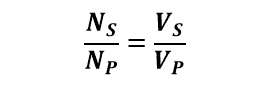
The formula for creating a Step-Down Transformer is as follows:
Where,
- Ns = number of turns in secondary
- Np = number of turns in the primary
- Vs = Voltage in secondary
- Vp = Voltage in primary
To operate the Transformer as a “Step-Down Transformer,” the number of turns in the secondary winding should always be fewer than the number of turns in the primary winding, i.e., Np>Ns.
Because the secondary winding has fewer turns, the total induced emf will be lower, and the secondary output voltage will be lower than the primary input voltage.\
Consider the following Step-Down Transformer scenario: the secondary turns [Ns] are 250, the primary turns [Np] are 5000, and the input voltage [Vp] is 240. The secondary voltage [Vs] can then be determined using the formula:
What Comprises a Step-Down Voltage Transformer?
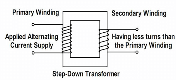
A primary and secondary winding and a magnetic core make up a step-down voltage transformer. In comparison to the secondary coil, the primary coil has more windings. Copper or aluminum conductors are commonly used in these coils. Here are a couple of things to think about:
- The primary winding is connected to the primary voltage, while the secondary winding is connected to the load, which draws the resulting stepped-down voltage/current.
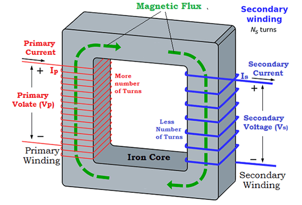
- The applied alternating current voltage pushes the primary winding. The alternating current in the primary winding causes the flux to be generated in the magnetic core around which the primary winding is coiled.
- The shared alternating magnetic flux now passes through the center of the secondary winding, causing a current to flow through the secondary winding wire.
- The number of windings that the flux flows through determines the second voltage level. The voltage is stepped down by the resulting turns ratio, calculated by multiplying the number of primary and secondary turns.
- The current is precisely proportional to the voltage, as we all know. As a result of the lower voltage, the current in the secondary coil is often higher (at the same power level). As a result, the primary coil’s current is often lower.
Transformers are frequently employed in the generation, transmission, and distribution of electricity. They’re also utilized in devices like doorbells to establish electrical separation for safety reasons. They also assist in operating many electrical and electronic gadgets by driving the motor.
Application of Step-Down Transformer
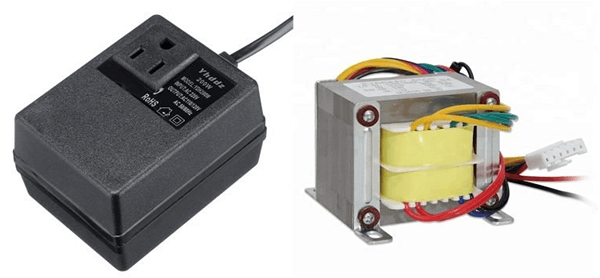
Step-down transformers are utilized in power adaptors and rectifiers to decrease the voltage efficiently. Electronic SMPS employ them as well.
There are also the following applications:
- Power transmission lines
- Welding machines
- Voltage stabilizers and inverters
Advantages of Step-Down Transformers
- Step-down transformers are highly efficient, with up to 99 percent efficiency in delivering the necessary output.
- We can achieve the desired output voltage without wasting a lot of energy.
- They are less costly and more dependable.
- They are capable of delivering high currents and low voltages.
Conclusion
Transformers are necessary for the national power grid to operate efficiently. These devices transform electrical power into the proper voltage to current ratios for long-distance transmission and local distribution. Transformers should be selected with caution due to their high price. Proper operation and maintenance can extend the transformer unit’s estimated lifespan.
Lastly, if you need any number of step-down transformers, contact us as ICRFQ, we are the best electrical components manufacturer in China.
If you want to find more Electronic Components Distributors, please check out the following articles:
Electronic Components Distributors In the USA
Electronic Components Distributors In UK
Electronic Components Distributors In China
Electronic Components Distributors In India
Electronic Components Distributors In Singapore
Electronic Components Distributors In Malaysia
Electronic Components Distributors In Vietnam
Electronic Components Distributors In South Korea
- Where to buy IC chips? The Best Guide? - March 26, 2024
- Breaking Down Barriers: Overcoming Obstacles in Cross-Border Electronic Component Trade - March 4, 2024
- Everything You Need to Know About Amplifier IC Chips - March 4, 2024


