
Last Updated on October 22, 2023 by Kevin Chen
What comes to your mind when you hear the term ‘core’? To most of us, we will assume that it is a very important system that controls all the activities of an object or a body.
That is exactly what a core is to a transformer. Whether it is a step-up or step-down transformer, a core is responsible for determining the output voltage of a transformer.
In this guide, we are going to look at everything you should know about a transformer core.
What is a transformer core?
A core is nothing more than a magnetic device that is used in a transformer. It is responsible for converting the input power into the output power.
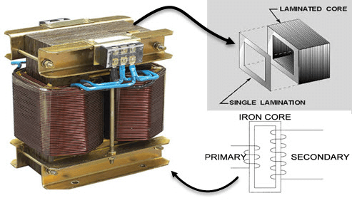
In a transformer, there are two coils of wire known as primary and secondary coils. When the input power is supplied, it passes through the primary coil and creates an electromagnetic field around it.
This electromagnetic field then induces a voltage in the secondary coil.
A core plays an important role in determining how much voltage will be induced in the secondary coil from this electromagnetic field.
What does a transformer core do?
The main job of a core is to increase or reduce the strength of an electromagnetic field that has been created by passing current through wires in coils. The stronger this magnetic field, the greater will be induced voltage in the secondary coil and vice versa.
These cores are made from ferromagnetic materials such as iron, steel, or nickel alloys to increase their strength so that they can create stronger magnetic fields when passing current through them. The type of core used in a transformer depends on the amount of voltage that is required to be induced in the secondary coil.
As we will discuss, transformer cores come in different types and have different specifications. Read on as we get deeper into the details about them.
Where is a core positioned in a transformer?
A core is positioned around the outside of the primary coil. It holds the wire that is wrapped around it to form the primary coil. The wire wrapped around it forms a magnetic field when current is passed through it due to inductance. The core material is chosen based on how much current can be passed through it before there is too much heat generated by the magnetic field and how much voltage can be induced in the secondary coil.
The core has a high permeability so there will be a large amount of flux (magnetic lines of force) when there is current flowing through it.
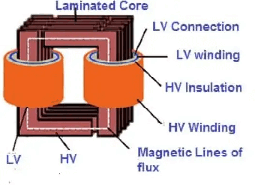
A transformer’s primary coil and secondary coils are wound on a laminated iron or steel core, which increases its strength. The more turns of wire wound on a core, the stronger becomes its magnetic field becomes.
Transformer core construction
A typical transformer core is made of steel or iron laminations. The core is made up of two parts: the laminated core and the bobbin.
The laminated core is a stack of thin, flat sheets of magnetic material with a hole in the center. It is insulated by an insulating material called a dielectric, which can be made from paper, plastic, mica, or fiberglass.
The bobbin is riveted to the laminated core and holds the wires that wind around it to form the primary and secondary coils.
Bobbins are usually constructed from aluminum or copper alloys with a high heat transfer rate.
At each end of the bobbin are two terminal lugs which are used to connect a wire to form primary and secondary coils in a transformer.
The ends of each coil are insulated so that only one wire touches another at any given time.
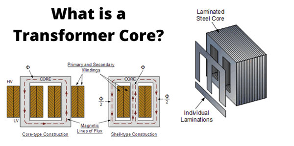
Transformer core design
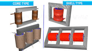
There are two major designs that characterize the construction of a transformer core. These are closed-core transformers and shell-core transformers.
What is the difference between these cores?
Closed-core transformer
This type of transformer core has a single magnetic path for the magnetic flux to flow through. The flux flows from the primary winding, through the core, and back to the secondary.
In this type of transformer core, there are no air gaps in between the individual turns of wire that form the primary and secondary coils.
In this type of transformer core, all windings are either on top of each other or wound around a common axis.
There is also another type of closed-core transformer that has all its windings lying at right angles to each other and which is called a flat-pancake-type transformer.
This type of transformer is used in applications where space is limited and where it is required that all parts be shielded against external interference by electromagnetic fields.
The main advantage of this type of transformer core is that they have very high magnetic coupling between their windings and therefore they have very high efficiency when compared to other types of transformers.
Shell-core transformers
This type of transformer is called a shell-core because it has a metal shell on the outside of its core.
Shell-core transformers are used in applications where a large amount of heat is generated because the shell on the outside of the core helps in dissipating this heat from inside the transformer.
Shell-core transformers are used in applications where it is required that there be a high degree of insulation between different sections of a circuit.
Shell-core transformers are also used to provide electrical isolation between different sections of an electric circuit.
The main disadvantage of this type of transformer is that they have low magnetic coupling between their windings and therefore they have low efficiency when compared to other types of transformers.
E core transformer
This is another common type of transformer core. Just as the name suggests, it has an E-shaped design.
This design is used to produce a magnetic field in the core that is perpendicular to the windings of the transformer.
Because of this, it produces a high degree of power transfer between windings and also produces a high degree of efficiency.
The main disadvantage of this type of transformer is that it has an E-shaped design which results in a low degree of magnetic coupling between windings and therefore they have low efficiency when compared to other types of transformers.
One other disadvantage with this type of transformer is that the E-shape design results in its inability to maintain a constant flux. The flux produced by this type of transformer fluctuates slightly. This can cause some electrical problems when this type of transformer is used in applications where high levels of accuracy is required.
In these applications, if there is any slight deviation from the correct value, then this can cause some damage to electronics or even result in a fire if used improperly.
Types of Transformer Core Materials
The core materials are chosen for their magnetic properties. The most commonly used core material is silicon steel. It has the highest permeability and the lowest loss factor of any known magnetic material. Iron and nickel have also been widely used because of their low cost, but they are less efficient than silicon steel cores.
Steel and iron are used in power transformers, while copper and nickel alloy cores are used in smaller power and distribution transformers.
The core is insulated using a dielectric material made from paper, plastic, mica, or fiberglass. Paper is the cheapest but it can crack when subjected to high temperatures or humidity over a long period of time.
Mica is more expensive but it does not crack under these conditions. Plastic is the most common choice because it is inexpensive and does not crack under either condition. Fiberglass, while expensive, is used in some high-end power transformers.
What makes a good transformer core?
When in the market looking for a transformer core, it is not just about getting any that is available. There are key features that characterize a good core for a transformer. These features include;
-The core should be made of iron or steel. The core should have a high saturation flux density. The flux density is the amount of magnetic flux that is produced in a given volume of material.
-The core should have a low permeability which means it will not allow leakage of magnetic flux into the surrounding environment.
-The core should be able to be designed to fit the size and shape of the transformer desired.
-The core must have good electrical insulation properties, i.e., it must not allow electrical current to leak from one side to another through the dielectric material used for insulating it from the magnetic path on each side.
-It must withstand heat or other environmental conditions as well as mechanical stress without breaking down or deteriorating.
– It must be able to withstand high voltages without being damaged by overloading, arcing, or any other fault conditions that could damage it in operation or result in fires or explosions due to overloading of its magnetic field.
-The core must be designed so that any leakage of current from one side to the other through the dielectric material is minimized.
– The design should minimize energy losses caused by eddy currents which are currents created by magnetism flowing around a conductor. These losses can be reduced by using materials with low losses and/or a high degree of saturation (as some ferromagnetic alloys do).
Why are ferrites used for transformer cores?
One of the properties that we have mentioned about a good core is that it should have ferrite properties. What does ferrite mean and why should it be considered?
The term ferrite simply means that the core is a substance that has iron in it. The more iron, the more ferrite. Ferrites are often used because they have some of the best properties for magnetic cores.
Ferrite materials have a high magnetic permeability. This means that they allow a great deal of magnetic flux to pass through them.
Ferrites are also high resistivity materials. This means that they have low electrical resistance.
Ferrites are also good conductors of electricity and heat. This means that they are very efficient at conducting electricity and heat away from the core.
Despite the fact that there is a high demand for ferrite for transformer cores, these materials also come with some demerits. The main problem with the ferrite core is they are easily saturated. This means that they have a high saturation flux density.
The saturation flux density is the amount of flux that can be carried by the core. This can cause core saturation and overheating.
Another problem with ferrite cores is that they are brittle. This means that they break easily under high loads. A transformer winding made of ferrite will also be more susceptible to damage from an explosion. A good way to prevent this is to use a steel core instead of ferrite.
It is also wise to make sure that the iron used in manufacturing the core is not contaminated by other metals such as lead, zinc, or cadmium.
Ferrite core vs Iron core transformers: What is the difference?
When it comes to buying cores for transformers, you are likely to encounter these two options. Ferrite and iron cores.
Iron cores are made of plain iron that has been coated with a ferrite material. The ferrite coating is in the form of a powder, which is usually made from a mixture of iron and nickel.
Ferrite cores are not as good as iron cores when it comes to saturation. This means that they can only carry a limited amount of flux.
The main benefit of the ferrite core is the higher insulation between windings. This allows the transformer manufacturer to create smaller transformers with less weight and lower voltage losses.
This makes them ideal for use in portable power supplies where weight and size are important factors. The downside to ferrite cores is that they are more brittle than iron cores. This means they will break easily under high loads.
This means that an iron core will be more suitable for use in transformers where high loads are required or where size and weight are important such as in portable power supplies, car batteries or backup generators etc.
Technical specifications for the transformer cores
You have decided to build a transformer from scratch. You have gathered all the other components and now it is time to get the core. Before you do so, several technical specifications should guide you when it comes to choosing the best core. They include
Core resistance
The first and most important specification will be the core resistance. This is the amount of current that is required to flow through a given area in order to produce a given voltage. This value will determine how much power the transformer will be able to produce.
Core inductance
It is important to pay attention to inductance. This value determines how much magnetic field a given coil of wire can produce. It also depends on how many turns are on each side of the coil and what kind of wire is used in its construction.
In order to get this value, you need to know how many windings are needed for your transformer and what kind of wire is used for each winding. This information can be obtained from industry standards or from manufacturer’s specifications sheet (which comes with each transformer).
Core speed
Core speed is the speed at which the core of the transformer generates a magnetic field. It is measured in hertz (Hz), which is one cycle per second. The higher the core speed, the more powerful your transformer will be. It is also important in determining the frequency of the alternating current which is generated.
Core voltage rating
Core voltage is the voltage that flows in the core of the transformer. It determines how much power your transformer can generate. The voltage is measured in volts. The higher the voltage rating, the more powerful your transformer will be.
Core temperature
Transformers are designed to work at different places under different conditions. For this reason, it will be difficult to ignore the temperature factor when it comes to choosing the core. Temperature affects the core voltage and can even affect the core speed. The temperature should be high enough so that the core will not overheat.
Core efficiency
Core efficiency measures the power loss that occurs in the core of the transformer. It is measured as a percentage and will have a positive or negative value. The higher the efficiency, the better it is for your transformer because it means there will be minimum losses in the core.
Core flux density
The flux density refers to how much magnetic field is generated by each turn of wire on a metallic coil. A high flux density means that more current will flow through an area of wire than other areas because there will be more magnetic field per turn of wire. A low flux density means that less current will flow through an area of wire than other areas because there will be less magnetic field per turn of wire.
Core width
Transformers come in different sizes, so is their core. Once you decide the dimensions of your transformer, you should do the same to the core.
The size of the core is measured in inches, and is usually specified by the manufacturer. The wider the core, the lower the loss resistance of the transformer.
However at some point, the core size becomes too wide to be practical for most applications (unless you are making a very high power device), and then you can use smaller cores for higher efficiency.
Core winding number (CWN)
The number of turns of wire makes up each turn of a coil on a transformer. Each turn should be connected to another turn with alternating polarity so that there is no short-circuit between turns. The more turns there are per turn, the more current it can handle before it heats up too much and starts to become inefficient.
Core weight
Some applications that use transformers are very sensitive to the weight factor. Since the core will be part of the transformer, it is important to keep its weight to the minimum.
So, when buying a transformer core, take time to verify its rated weight. It should not be too heavy beyond the required minimum.
Keep in mind that the core weight is affected by several factors including the material and size of the core.
Transformer core geometry
The shape of the core affects its performance in terms of efficiency, capacitance, and inductance. Some applications require a different core geometry to achieve a certain level of performance. For example, a transformer may have to be designed to handle a large amount of power and be able to maintain low voltage at high current levels (e.g., power levels above 100 kVA). In such cases, the core may need to be shaped like an I-beam instead of a rectangular cylinder (if it has to be rectangular).
Another example is where the core needs to have a very low inductance in order for other components in the system (such as reactors and transformers) to operate efficiently without interference from stray magnetic fields that might affect their operation.
Where to buy transformer cores
Time to make that vital purchasing decision. Where can I get the best transformer core? This is one of the most common questions asked by purchasers of transformers.
The best place to get a core is from the transformer manufacturer. This is because they know where to get the core that will perform best for each type of application. So if you are buying a new transformer, do not buy it off the shelf and pay through the nose for it.
Go to the manufacturer’s website and look at their core selection or contact them directly if they don’t have an online store. They may be able to save you money.
It will even be easier if you go through a sourcing agent. This is vital if you want to find the best transformer core manufacturer. A reputable electrical components sourcing agent in China such as ICRFQ will ensure that you get the best cores for your transformers. Simply contact us and we will get the job done.
If you want to find more Electronic Components Distributors, please check out the following articles:
Electronic Components Distributors In the USA
Electronic Components Distributors In UK
Electronic Components Distributors In China
Electronic Components Distributors In India
Electronic Components Distributors In Singapore
Electronic Components Distributors In Malaysia
Electronic Components Distributors In Vietnam
Electronic Components Distributors In South Korea
- Where to buy IC chips? The Best Guide? - March 26, 2024
- Breaking Down Barriers: Overcoming Obstacles in Cross-Border Electronic Component Trade - March 4, 2024
- Everything You Need to Know About Amplifier IC Chips - March 4, 2024


