
Last Updated on October 27, 2023 by Kevin Chen
Electric circuits are everywhere and are essential for almost every aspect of our lives. These circuits are also very important as they can be used to power practically anything we can think of, from a light bulb to a refrigerator.
Even though these basics are common knowledge, it’s important to understand why and how these circuits work. This guide will provide an overview of the different types of electric circuits and their uses.
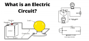
What can we define an electric circuit to be?
An electric circuit is a path of electrical charges that are transferred through an electrical device. These circuits can be used to transfer energy from one point to another and this energy can be used for many different purposes.
This includes powering electronic devices such as TVs or phones, powering an engine, lighting up a lamp, or charging a battery. In some cases, electric circuits are even used to create sparks that ignite a spark plug in the car engine.
Types of electric circuits
Electric circuits are divided into different types and classified under different categories. We are going to look at each type of these circuits and their key features.
Series circuit
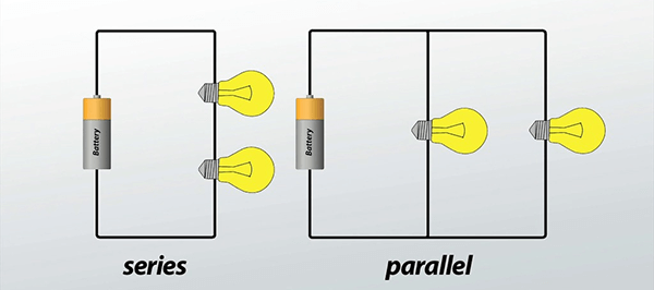
In this type of electric circuit, the loads and other electrical components are connected in series. This simply means that the loads are connected in a line.
There is only one path through which the electric current flows in the circuit.
There are no other branches connected to the circuit or from the power source.
In the series circuit, the resistance of the loads is inversely proportional to the number of loads in the series.
The current flowing through the circuit is directly proportional to the voltage applied to it.
Series circuits are considered to be one of the most common electric circuit types.
For example, in a simple light bulb circuit, there are two light bulbs connected in series. The resistance of each bulb is directly proportional to the number of bulbs connected in series. As there are 2 bulbs, their resistance is twice that of one bulb and so is their current consumption too.
Parallel Circuit
In this type of electric circuit, loads and other electrical components are connected in parallel.
In this case, there are more than one paths through which the electric current flows in the circuit.
There can be more than two branches from different sources (like different batteries or solar cells) that make up multiple branches for current flow through a parallel circuit. However, each branch has only one path through which electric current flows.
The current flowing through the circuit is directly proportional to the voltage applied to it.
In a parallel circuit, there are more than one paths through which electric current flows in the circuit.
There can be more than two branches from different sources (like different batteries or solar cells) that make up multiple branches for current flow through a parallel circuit. However, each branch has only one path through which electric current flows.
Circuit theory uses Kirchhoff’s Voltage Law, Ohm’s Law, and Ampere’s Law in combination with Maxwell’s equations to explain electrical circuits:
The voltage across a resistor is proportional to the current through it and thus is equal to the current multiplied by the resistance. The voltage across a resistor will be the same whether that current comes from a battery, light bulb, starting motor, or any other source. This can be seen by making a series of connections of resistors and connecting them in parallel:
Because there are two paths for current flow in this circuit, there are two voltages across each resistor. The magnitude of these voltages is determined by the voltage source (in this case, battery) and the resistance of each resistor.
Series-Parallel circuit
From the name, this one is a combination of both series and parallel circuits. This implies that certain elements of the circuit are connected in series and others are connected in parallel. The combination of these two forms of connections is what makes the circuit an integrated one.
In this case, the voltage is the same throughout the circuit because there are no resistors at the ends of the circuit. As a result, there are no voltage drops in this type of circuit.
Star-delta circuit
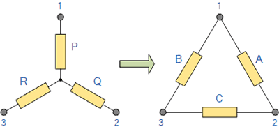
Here, elements are connected in an undefined manner-They are not in series, parallel, or series-parallel. This is because the elements are connected in a star configuration. In this case, the voltage is the same throughout the circuit because there are no resistors at the ends of the circuit. This type of circuit is commonly used in amplifiers and radio.
Pure resistive circuit
In this case, there is no current flowing through the resistor. This means that current is not flowing through the elements of the circuit. In this case, no voltage drop occurs across any element in the circuit. This type of circuit is commonly used in rectifiers and to measure high-frequency voltages such as radio signals.
Pure capacitive circuit
This is a type of circuit that contains a pure capacitor with a defined capacitance. Capacitance is defined as the ability of a capacitor to store charge and it usually depends on the area of the capacitor. Dielectric materials are used for separating the conductive plates.
In this type of circuit, the voltage source facilitates the charging and discharging of the capacitors.
Resistive, Inductive (RL Circuit)
This circuit consists of a resistor and an inductor. When a voltage is applied to the circuit, current flows through the resistor and cannot flow through the inductor.
As a result, there is no current flowing through the inductor. To make this circuit, we need to use a coil of wire (inductor) with a cross-section of circular or rectangular shape which is wound around a non-magnetic metal core (resistor). The purpose of this circuit is to store energy in order to produce electrical power.
Resistive, Capacitive (RC Circuit)
This type of circuit is similar to the RL circuit. In this circuit, the capacitor is used instead of the inductor. The only difference is that in RC circuit, current flows through the resistor while in RL circuit, current flows through the inductor.
Inductive, Capacitive (IC Circuit)
In this type of circuit, an inductor is connected in series with a capacitance (capacitor). The voltage across the capacitor causes a current to flow through it. This current charges and discharges the capacitor. Therefore, this device can produce energy from stored charges by means of induction.
Resistive, Inductive, Capacitive (RLC Circuit)
In this circuit, three components are used. The resistor is called the series inductor and the capacitor is called the shunt inductor. Both these components are connected in series with each other and form an RLC circuit.
The capacitor discharges through the resistor while the current flowing through the inductor creates an electric field which causes a current to flow through it. This current charges and discharges the capacitor in a cyclic manner i.e., it oscillates back and forth between charging and discharging states. This makes RLC circuits very useful for applications like radio frequency power supply, oscillator, modulator, etc.
Linear and Non-Linear Circuits
A linear circuit is a type of electrical circuit that is characterized by the constant supply of parameters. These can be constant resistant capacitance, inductance, resistance, and frequency among others. In other words, these parameters don’t change regardless of the supply voltage.
Non-linear circuits are circuits that change their parameters when the supply voltage changes.
Unilateral & Bi-lateral Circuits
A unilateral circuit is a type of circuit in which the overall function of the circuit will change the moment that the direction of the current or voltage will change. Otherwise, the circuit will continue functioning as designated.
In other words, a unilateral circuit allows current to flow in one direction only.
Bilateral means different directions. In this circuit, the current is allowed to flow in any direction and the functioning of the circuit will not be affected.
Common terms associated with types of circuits
There are several terms that are often used or associated with different types of circuits. Let’s look at some of them;
Open and closed circuits
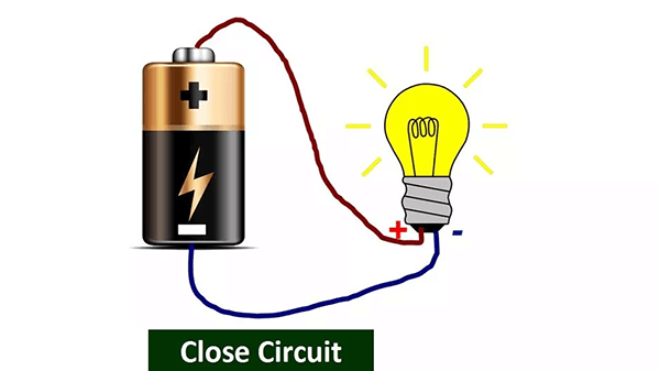
An open circuit simply means that the circuit is not complete, or there is no return path for the current to flow. A circuit is usually open when the conductor or wire has been damaged hence cannot complete the loop for the current.
A closed circuit is one that is complete, or all the paths for current flow have been tested and found to be functional.
Short circuit
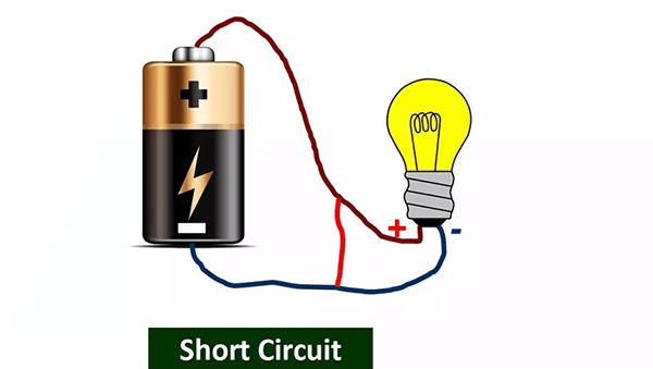
A short circuit is one that has a return channel for current to flow through. In this circuit, the voltage tends to infinity while the current heads to zero. A short occurs when the two conducting lines are accidentally joined resulting in a maximum flow of current. This is the main reason why the short circuit is always deemed dangerous.
Active and passive circuit
When do we say a circuit is active and when do we say is passive?
An active circuit is one which which contains Electro motive forces (EMF). On the other hand, a passive circuit is one that does not have an electro motive forces (EMF).
Parts and components of an electric circuit
Regardless of the circuit types, let’s look at the parts and components that make up a typical electric circuit.
-Node: A node is an electrically conductive point on a circuit.
-Load: A load is a device which is used as part of the circuit.
-Source: A source of electric current is the battery. If a battery is not present, then the other components in the circuit are sources of current.
-Voltage: Voltage is the electrical pressure that pushes electrons through an electric circuit. The voltage in an electric circuit can be measured in volts (V) or millivolts (mV).
-Current: Current, or flow of electrons, can be measured in amperes (A) or milliamperes (mA). The unit for measuring current is ampere-hour (Ah), abbreviated as “amp-hr”. The unit for measuring electrical energy flow is watt-hour (Wh), abbreviated as “watt-hr”. For example, one amp-hr equals one watt-hr and ten amp-hr equals one watt.
-Node: A node is an electrically conductive point on a circuit where two elements are joined or meet. For example, it can be a point where the resistor and inductor join.
-Branch: This is a segment or section of an electric circuit where the a circuit occurs between two junctions. A branch can have one or several endpoints.
-Loop: A loop is a section of the circuit that contains several meshes. Usually, the circuit has a single loop, but it can also have several loops.
-Mesh: The mesh of an electric circuit is the smallest unit of electronic information in which electrons flow. A mesh can be a single point, a single loop, or an entire branch.
-Direction: The direction of current flow through an electric circuit is from negative to positive or vice versa. Electric current flows in one direction only and cannot flow in both directions at the same time.
Which type of electric circuit should I use?
Now that you know the different types of electric circuits, what next? You can go ahead and implement whichever type of circuit you think will fit into your application.
First, analyze your application requirements. The next step is to identify the type of current flow in your application.
Now that you have identified the type of current flow in your application, you can design a circuit that will satisfy the requirements. To do this, conduct an analysis and design of your circuit.
The next step is to craft a circuit diagram from your analysis and design. This should follow the same format as that of a traditional electrical schematic diagram but with some unique elements added into the mix (such as microcontrollers).
The final step is to build a physical prototype according to the schematic diagram created by yourself or someone else.
The prototype will need to be tested before it can be used in production mode. For this, you can either test it on paper first, then build it on actual components and test it again.
If you want to find more Electronic Components Distributors, please check out the following articles:
Electronic Components Distributors In the USA
Electronic Components Distributors In UK
Electronic Components Distributors In China
Electronic Components Distributors In India
Electronic Components Distributors In Singapore
Electronic Components Distributors In Malaysia
Electronic Components Distributors In Vietnam
Electronic Components Distributors In South Korea
- Where to buy IC chips? The Best Guide? - March 26, 2024
- Breaking Down Barriers: Overcoming Obstacles in Cross-Border Electronic Component Trade - March 4, 2024
- Everything You Need to Know About Amplifier IC Chips - March 4, 2024


