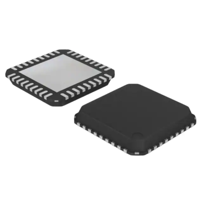
USB2514B-I/M2
Part Number: USB2514B-I/M2
Manufacturer: Microchip Technology / Atmel
Description: USB Interface IC 4-Port USB 2.0 Hi-Speed Hub Cont
Shipped from: Shenzhen/HK Warehouse
Stock Available: Check with us
ICRFQ.com - Electronic Components Distributor in China Since 2003

Part Number: USB2514B-I/M2
Manufacturer: Microchip Technology / Atmel
Description: USB Interface IC 4-Port USB 2.0 Hi-Speed Hub Cont
Shipped from: Shenzhen/HK Warehouse
Stock Available: Check with us
| Datasheet | |
|---|---|
| Category | Integrated Circuits (ICs) |
| Family | Interface – Controllers |
| Manufacturer | Microchip Technology |
| Series | * |
| Packaging | Tray |
| Part Status | Active |
| Protocol | USB |
| Function | Hub Controller |
| Interface | USB |
| Standards | – |
| Voltage – Supply | 3 V ~ 3.6 V |
| Current – Supply | 70mA |
| Operating Temperature | -40°C ~ 85°C |
| Package / Case | 36-VFQFN Exposed Pad |
| Supplier Device Package | 36-SQFN (6×6) |
The Microchip USB2514B-I/M2 hub is a family of low-power; customizable MTT (multi-transaction translator) hub controller IC components designed for embedded USB systems. The letter x in the component number specifies the number of downstream ports that are accessible, and the letter B denotes that battery charging is a supported feature. On all of the enabled downstream ports, the Microchip hub can support low-speed, full-speed, and high-speed (if it is functioning as a high-speed hub) devices connected to the downstream ports.
The Microchip USB2514B-I/M2 hub family is a collection of MTT (multi-transaction translator), programmable hub controller ICs. These ICs consume very little power and can handle several transactions simultaneously. The hub is fully compliant with the USB 2.0 Specification [1, and it features downstream ports for USB solutions that are integrated]. Every one of the hub controllers can act as a full-speed or full-and-hi-speed hub when it is attached to an upstream port. The hub can support downstream devices operating at low, full, and high speeds when functioning as a high-speed hub. The hub incorporates all of the necessary resistors for the USB ports into its design. This includes all the pull-down and pull-up resistors on the D+ and D- pins. Also included are all of the series termination resistors. Internal pull-up resistors can be found on the over-current sensing inputs located on the ports facing downstream.
The programmable capabilities available on the USB251xB/xBi hub family include the following:
The implementation of a Transaction Translator (TT) that is specific to each port. Dedicated TTs make it easier to keep data throughput constant and at full speed no matter how many active downstream connections there are.
It provides configurable port mapping and disables sequences. To enable diverse platform designs with the least amount of work possible, the downstream ports of a USB251xB/xBi hub can be disabled in any sequence and reordered however the user sees fit. The port numbering scheme of the USB host controller is matched up with the port numbering scheme of the USB251xB/xBi hub controller if a port on the hub is disabled and the hub controller is used.
This feature allows for direct alignment of USB signals (D+/D-) to connections, which helps to eliminate uneven trace length as well as crossover of USB differential signals on the printed circuit board (PCB).
It makes it possible to configure four different USB signal drive intensity levels for use in downstream port transceivers. PHYBoost will also try to restore the USB signal’s integrity.
As soon as the power on reset and the hardware configuration process is over, a downstream port equipped for battery charging will turn on the port power and begin charging the battery. The hub does not need to be enumerated, and the VBUS DET signal does not have to be asserted to enable the port power. Under these circumstances, it is possible to charge the battery in the fully operational state and in the S3, S4, and S5 system power states.
The USB Battery Charging Specification does not interfere with the ordinary working of USB, which enables a device to execute battery charging at any time without constraints. A port that allows for charging batteries must have the capacity to provide a current of 1.5 amps when connected to the VBUS. In most cases, the maximum amount of current that a standard USB port power controller can safely handle is 0.8 amps. This is the point at which the controller will signal an over-current condition. Because of this, a power supply that operates at 5 volts, a port power controller, or over-current protection devices need to be selected to accommodate the higher current requirement compared to normal USB hub designs.
As soon as the hardware configuration procedure is finished, the USB251xB/xBi will enable VBUS by asserting the port power (PRTPWR). This will allow the bus to be used. PRTPWR will be turned off to prevent the circuitry from overloading if the port determines that an excessive current is being drawn. PRTPWR can only be activated from the host or toggling RESET N if an over-current condition is detected when the hub is not being enumerated. This prevents the hub from being damaged. These behaviors protect the hub from continuous short-circuit circumstances and offer battery charging even while the hub is not being enumerated. If the short circuit condition remains after the hub has been connected to a host system, the user will be informed that one of the ports is experiencing an over-current condition. In any other case, the host system will have PRTPWR switched on, and the ports will function normally.
Contact ICRFQ, your one-stop shop for electronic sourcing components in China, if you require further information or like to place an order for the USB2514B-I/M2. We will work hard to ensure you get the best possible products at affordable prices.
WhatsApp us