
Last Updated on May 12, 2022 by Kevin Chen
The op-amp inverting amplifier circuit is simple to develop and implement with only more electronic components. The op-amp inverting amplifier requires two extra resistors to be incorporated in the electronic circuit design process in its most basic version. This keeps the circuit simple and straightforward to construct while still delivering good performance.
This inverted amplifier can also be used as a virtual earth mixer or summing amplifier, but its input impedance is lower than the inverting configuration. This op-amp circuit works well as a summing amplifier in audio mixers and other electrical circuits where voltages must be added together. Many people prefer the op-amp inverting amplifier because it is simple to create and performs well. Continue reading to learn more about the op-amp inverting amplifier
What is an Inverting Op-Amp
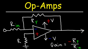
A DC-coupled high-gain electronic voltage amplifier having a differential input and, usually, a single-ended output is known as an operational amplifier (op-amp or op-amp). In this setup, an op-amp produces an output potential 100,000 times greater than the difference in potential between its input terminals (relative to circuit ground). Operational amplifiers arose from analog computers, where they were utilized to conduct mathematical operations in linear, nonlinear, and frequency-dependent circuits.
Because of its versatility, the op-amp is a popular building component in analog circuits. Negative feedback allows the gain, input, and output impedance, bandwidth, and other parameters of an op-amp circuit to be dictated by external components rather than temperature coefficients or technical tolerance in the op-amp itself.
Inverting Operational Amplifier Configuration
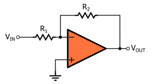
An inverting op-circuit amp’s diagram is given below. The negative terminal is connected via feedback to create a closed-loop function in this circuit. When working with op-amps, we must remember two important rules: there is no current flow in the input terminal, and V1 is always equal to V2.
This is since the positive input terminal is grounded at OV. The op-amp is connected using feedback to generate a closed-loop operation in the above arrangement. While working with operational amplifiers, there are two crucial guidelines: “No current flows into the input terminal” and “V1 always equals V2.”
However, because the input junction and feedback signal ‘X’ are at equal voltage, the two rules mentioned above are broken in practical op-amp circuits. The junction is a “Virtual Earth” when the positive input voltage is zero volts. As a result of this virtual earth, the input resistance of the op-amp is equal to the input resistor value (Rin).
The ratio of the two external resistors can be used to control the closed-loop gain of the inverting op-amp. The non-inverting terminal of the op-amp is connected to the ground after the input signal is applied through the ‘Ri’ resistor to the inverting terminal of the op-amp. A feedback system is also included to keep the circuit stable. A feedback resistor ‘Rf’ can now be used to adjust the output.
Inverting Op-Amp Waveforms
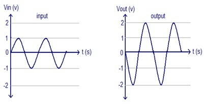
The input and output waveforms of inverting op-amps are given below. Assuming the amplifier’s gain and the sine wave as an input signal, the waveforms below can be produced. The following waveforms clearly show that the output is twice as large as the input (Vout = Av * Vin) and that the phase is the opposite of the input.
Inverting Op-Amp Working & Operations
The voltage gain provided by the circuit as mentioned above is calculated as follows:
Av = Vo/Vi
Where,
Vi-V1 = IiRi
V1-V0 = IfRf
However, we know that a perfect operational amplifier has limitless input impedance because no current flows into its input terminals. I1 = I2 = As a result, Ii is the same as If. So,
Vi-V1 = IfRi
V1-V0 = IfRf
We know that the voltage at two op-amp inputs is always equivalent to a perfect operational amplifier.
The voltage that appeared at the non-inverting terminal is V1 = V2= 0 since the non-inverting terminal is grounded. So here’s the equation:
Vi-0 = IfRi
0-Vo = IfRf
We can deduce the following from the equations mentioned above:
-Vo/ Vi = IfRf/ IfRi
Vo/ Vi = – (IfRf/ IfRi)
Vo/ Vi = – (Rf/Ri)
Vout can be obtained by changing this equation.
Vout/ Vi = – (Rf/Ri)
Vout = – (Rf/Ri) x Vin
An inverting op-voltage amp’s gain is equal to
Inverting Op-Amp Gain (Av) = – (Rf/Ri)
The percentage of the ‘Rf’ to the ‘Ri,’ including the negative sign denoting the reverse phase, can calculate the voltage gain of an inverting amplifier. In addition, the input impedance of the inverting amplifier is ‘Ri.’
These amplifiers have good linear qualities, similar to DC amplifiers, making them perfect. Furthermore, they are commonly used in Transresistance and Transimpedance Amplifiers to convert the i/p current to the o/p voltage.
The output voltage (Vout) equation Vout = Vin x Gain illustrates that the op-amp circuit is linear for a fixed gain of an amplifier. As a result, this property comes in handy when converting a low sensor output to a greater voltage.
Voltage Characteristics
The voltage characteristics of an inverting amplifier are depicted in the graph below. It’s worth noting that the output voltage, Vout, is negative when the input signal, Vin, is positive. Furthermore, the output voltage will fluctuate linearly after the applied input voltage.
Once the amplitude of the input signal exceeds both of the supplied power supply to the op-amp, this characteristic will saturate; otherwise, the output will become constant.
+VCC = + VSAT & –VCC = -VSAT
Why is Inverting Op Amps better than Non-Inverting Op Amps?
The offset voltage is less than a few mV because it is included in the output of an inverting op-amp. However, the offset voltage of a non-inverting op-amp can be modified through the non-inverting gain, and this voltage is again included in the output voltage.
When compared to non-inverting amplifiers, inverting amplifiers provide more system stability. Negative feedback is used in inverting amplifiers, which is always required for a stable system.
Advantages
Some of the advantages of inverting amplifiers are listed below.
- They are inexpensive.
- Small size • Versatility • Dependability • Flexibility
- This op-two amp’s input terminals are always zero. Furthermore, just the differential mode signal will be present.
- The inverting amplifier device has a high anti-interference capability and employs negative feedback.
- There is a very high gain factor.
- These op-output amps will be out of phase with the input signal.
Disadvantages
The following are some of the downsides of inverting amplifiers.
- The input impedance is low (equal to r1)
- It has a lot of gains, but the feedback must be kept as clean as possible.
- Because the small number will be multiplied and obtained at the output, the input signal should not include noise.
Inverting Op-Amp Applications
Use in electronics system design
Whether the amplifiers are integrated or discrete circuits, using op-amps as circuit blocks is considerably easier and clearer than identifying all of their circuit elements (transistors, resistors, and so on). Opto amplifiers can be employed as ideal differential gain blocks in the first approximation. After that, limitations can be set on the allowed range of parameters for each op-amp.
All electronic circuits are designed along the same lines. A specification specifies what the circuit must accomplish and the permissible limits. For example, the gain might have to be 100 times with a 5% tolerance but a drift of less than 1% across a certain temperature range; the input impedance might have to be one megohm; and so forth.
A basic circuit is created frequently with circuit modeling (on a computer). The design parameters are then met with commercially available op-amps and other components that meet the design specifications within the specified tolerances at a reasonable cost. If not all criteria are met, the specification may need to be changed.
After that, a prototype is produced and tested, with adjustments to fulfill or improve the specification, change functionality, or reduce cost.
Applications without using any feedback
The op-amp is being utilized as a voltage comparator, in other words. Note that if speed is necessary or a broad range of input voltages is available, a device built primarily as a comparator may be preferable because such devices may quickly recover from full-on or full-off (“saturated”) states.
A voltage level detector is obtained when a reference voltage Vref is applied to one of the op amp’s inputs. The op-amp is set up as a comparator to detect a positive voltage in this scenario. When the detected voltage, Ei, is fed to an op amp’s (+) input, the result is a non-inverting positive-level detector: when Ei is above Vref, VO = +Vsat; when Ei is below Vref, VO equals Vsat. When Ei is applied to the inverting input, the circuit becomes an inverting positive-level detector: VO equals Vsat when Ei is above Vref.
A zero voltage level detector or (Ei = 0) can turn the output of a function generator’s sine wave into a variable-frequency square wave, for example. The zero-crossing detector’s output will be square if Ei is a sine wave, triangle wave, or any symmetrical wave around zero. Zero-crossing detection could also help start TRIACs at the right time to decrease mains interference and current spikes.
Positive-feedback applications
Positive feedback, which returns a portion of the output signal to the non-inverting input, is another common arrangement of op-amps. The Schmitt trigger, a comparator with hysteresis, is one of its most common applications. Triangle-wave oscillators and active filters are two examples of circuits that use positive and negative feedback around the same amplifier.
The open-loop level detectors discussed above will have a delayed response due to their broad slew range and lack of positive feedback. External overall positive feedback can be used, but it significantly impacts the accuracy of the zero-crossing detection point (unlike internal positive feedback that can be used in the latter stages of a purpose-designed comparator). The frequency of Ei for sine to square wave converter using a general-purpose op-amp, for example, should be below 100 Hz.
Frequently Asked Questions
Why is the inverting amplifier used?
Because the slew rate of an inverting Op-Amp is higher than that of a non-inverting type setup, it is commonly employed for high-frequency applications where high i/p impedance is not required.
Why is a unity gain amplifier used?
A voltage follower, also known as a voltage buffer, a unity gain amplifier, or an isolation amplifier, is a device that follows a cheval. The output voltage (Vo) of a voltage follower circuit is equal to the input voltage (Vin). As a result, this amplifier’s gain is 1, not affecting the incoming signal.
What is the formula for inverting an amplifier?
The formula is inverting amplifier (Av) = – (Rf/Ri).
How do you utilize an op-amp as a non-inverting amplifier?
By connecting the input to the op-amp’s positive terminal and the op-amp’s output voltage signal as feedback to the input of the inverting terminal, an op-amp can be utilized as a non-inverting amplifier.
Last but not Least
Op-amps are utilized in today’s electronic devices, including consumer, industrial, and research products. Many typical IC operational amplifiers are merely a few cents, but, in limited quantities, certain integrated or hybrid operational amplifiers with unique performance criteria might cost over $100. Op-amps can be packed as individual components or used as parts of larger integrated circuits.
The operational amplifier (op-amp) is one type of differential amplifier. Differential amplifiers include the fully differential amplifier (like an op-amp but with two outputs), the instrumentation amplifier (usually made up of three op-amps), the isolation amplifier (like an op-amp but with tolerance to common-mode voltages that would destroy an ordinary op-amp), and the negative-feedback amplifier (usually built from one or more op-amps and a resistive feedback network).
Conclusion
This overview of an inverting op-amp is often known as an inverting operational amplifier. In analog electrical circuits, operational amplifiers are commonly employed as basic components. As a result, it is employed in filtering, signal conditioning, and various arithmetic processes. To boost the voltage level for the signal applied, several electrical components are utilized between the two terminals of the operational amplifier. We hope that you have found this information to be helpful.
For more info on Op-Amp or the purchase of electrical components, contact us at ICRFQ. At ICRFQ, we are known to be the best electrical components manufacturer in China.
If you want to find more Electronic Components Distributors, please check out the following articles:
Electronic Components Distributors In the USA
Electronic Components Distributors In UK
Electronic Components Distributors In China
Electronic Components Distributors In India
Electronic Components Distributors In Singapore
Electronic Components Distributors In Malaysia
Electronic Components Distributors In Vietnam
Electronic Components Distributors In South Korea
- Where to buy IC chips? The Best Guide? - March 26, 2024
- Breaking Down Barriers: Overcoming Obstacles in Cross-Border Electronic Component Trade - March 4, 2024
- Everything You Need to Know About Amplifier IC Chips - March 4, 2024


