TPS1HA08CQPWPRQ1
Part Number: TPS1HA08CQPWPRQ1
Manufacturer: Texas Instruments
Description: MCU EVAL
Shipped from: Shenzhen/HK Warehouse
Stock Available: Check with us
ICRFQ.com - Electronic Components Distributor in China Since 2003

Part Number: TPS1HA08CQPWPRQ1
Manufacturer: Texas Instruments
Description: MCU EVAL
Shipped from: Shenzhen/HK Warehouse
Stock Available: Check with us
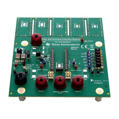
The HSS-MOTHERBOARDEVM from TI is an evaluation module that tests the company’s 50-m Ron high-side switch products. The TPS27SA08, the TPS1HA08-Q1, the TPS2HB08-Q1, the TPS2HB16-Q1, the TPS2HB35-Q1, and the TPS2HB50-Q1 are a few examples of devices that fulfil this criterion. Other examples include: Although the components shown on this board are not included, it is possible to solder them onto the sample daughter card provided and then use the card in conjunction with the main motherboard. This manual covers the EVM’s connectors, test points, design, BOM, and board layout.
The high-side switch device’s associated daughter card can be placed into a central socket on the Texas Instruments HSS-MOTHERBOARDEVM evaluation module. This socket is located in the middle of the module. The EVM can accommodate many single-channel and dual-channel high-side driver applications, including those with low Ron (50 m) requirements. With the help of this EVM, testing and diagnosing the performance of low-Ron high-side switches while driving resistive, capacitive, and inductive loads is much simpler. The evaluation of the switches should also become less complicated thanks to this system’s efforts.
The EVM consists of a central motherboard in addition to several daughter boards located at various locations throughout the device. The motherboard combines all of the necessary components, such as connectors, jumpers, and test points, among other things. To handle the low Ron family of switches that are part of TI’s high-side switch portfolio, the daughter board features numerous footprint possibilities. Because the one-channel device (TPS1HA08-Q1) has an NC pin in that location, the daughtercards will work for all of the devices in the system and will have limiting resistors for the channel devices (TPS2HBxx-Q1).
There are two daughterboard footprints, one with 24 pins and the other with 16 pins. Both of these kinds of impressions can be used. To finish the installation, the one-panel board needs to be removed, a device needs to be soldered onto the primary footprint, and the motherboard needs to be attached. Only then can the installation be declared finished.
Note: When soldering the device down, care must be taken since the primary power pad on the rear needs to be soldered correctly to avoid affecting the device’s functioning.
The resistors that limit the current flow are located on the underside of the daughterboard. They are all packaged in an 0805 format and come in 10-k units. It is possible to replace the resistor with one with a different value to get the required current limit value. In addition, the second resistor should be depopulated for the devices with a single channel.
The Texas Instruments HSS-MOTHERBOARDEVM is a tool that supports designers in assessing the operation and performance of various Texas Instruments devices, such as the TPS2HB16-Q1, TPS27SA08, TPS1HA08-Q1, TPS2HB35-Q1, TPS2HB08-Q1, and TPS2HB50-Q1 modules. These devices are high-side switches that include complete high-side protection, a charge pump, and integrated NMOS power FET. In addition, these devices have a full complement of security on the low side.
Features such as comprehensive diagnostics and current sensing with a high degree of accuracy make it feasible to implement intelligent load regulation. The load current and the device’s temperature status can be reported via the device’s diagnostic capabilities with an analog sense output pin labelled SNS.
The value of the parameter being utilized at the moment is directly proportional to the amount of current being pulled from the SNS pin. A pulldown resistor connected to the SNS pin generates a voltage proportional to the specified parameter. Turning off the diagnostics to multiplex the sensing pin on several devices is possible. This can be done in a variety of ways.
Suppose IOUT exceeds the current limit threshold, denoted by ICL = KCL / RILIM. In that case, the device can either turn off immediately or continue to operate while imposing an IOUT restriction. Because of the flexibility with which any device can be populated on the HSS-MOTHERBOARDEVM, it is possible to implement various use cases. This is made possible because the device can be placed either on the snap-off cards or the footprint directly on the board.
The thermal shutdown or energy limit protection feature may be activated if the device is left active for an extended time, as this results in a significant quantity of power being wasted by the device (and sets limitations on IOUT). It is recommended that the user examine the data sheet of the equipment to acquire information regarding the type of current that may be utilized with the device without risk.
High-precision current sensing makes real-time monitoring and other diagnostics possible without extra calibration. The SNS pin needs only 1/5000th of the load current when using a current mirror. The SNS pin converts the current source into voltage by connecting a 1 k resistor, R1. Applying the equation, VSNS = 1,000 IOUT / 5,000 will get the voltage.
The HSS-MOTHERBOARDEVM is equipped with sizeable footprints that can accommodate TVS diodes if they need any transient testing. While SMB footprints are D3 and D4, the SMC footprints are D4, D5, and D6. If required, C4 and C11 capacitor footprints can be occupied.
Are you prepared to order the TPS1HA08CQPWPRQ1, or are you more interested in more details? Contacting ICRFQ is the best course of action if you’re trying to find Chinese-made electrical components online. We will go above and beyond to ensure you receive the best products for the lowest cost.
WhatsApp us