Last Updated on October 22, 2023 by Kevin Chen
The circuit breaker is tripped by a distance relay, an essential component. Rather than the circuit breaker, the relay can trip the circuit in low-rated power system circuits. The circuit breaker and relay working together protect distribution and transmission systems. Relays are divided into categories based on how they operate. We have relays that operate using the difference in current, current, and frequency, such as overcurrent, differential, and frequency relays.
The pickup quantity is determined based on the operational quantity. The operational quantity in a distance relay is impedance; moreover, the relay functions in accordance with the transmission line’s impedance. The transmission line’s impedance is determined based on the defect’s location, the voltage at the moment of the problem, and the fault current. Additionally, the relays are categorized as mho relays, reactance relays, etc., depending on the transmission line’s length or the protection distance. These relays are widely utilized, have several benefits, and are the most reliable in all fault circumstances.
What is Distance Relay?
Distance relays may also be referred to as distance protection or impedance relays. Their operation depends on the separation between the damaged portion’s impedance and the relay’s location. This is a device that manages voltage. When the impedance value at the defective spot is less than the impedance value set for the relay, the relay is used to measure the impedance there. As soon as this occurs, the device signals the circuit breaker, instructing it to close the contacts without following the tripping command.
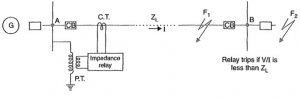
This remote relay consistently monitors the line current and voltage flow through PT & CT in the appropriate directions. The relay is in working order when the voltage and proportional current voltage is low. The following diagram represents a distance relay: Direct overcurrent relays pose some challenges in dealing with these problems since power systems become more complicated and fault current varies depending on generation and system setup. Distance relay settings remain constant when compared to modifications outside the protected line.
Distance Relay Theory
Overvoltage or overcurrent relay shortcomings have led to a significant need for distance relay. The fundamental idea is that the protection can be offered with variations depending on the sort of defect and how far away it is. As an illustration, the reach of the three-phase (LLL) fault is significantly greater than the reach of the line to ground (LG) fault. Therefore, the pickup point of overcurrent relays needs to be changed if we want to protect up to a specific limit. This is impossible since relays can only handle a certain amount of pickup current.
The main drawback of overcurrent relays is that the length of the protected line depends on the fault and the fault current. Similarly, the source impedance affects how far away protection is. The distance reached by a specific type of defect increases with decreasing source impedance. Because of this, source impedance also affects the length of time the overcurrent relay protects the line.
The produced voltage is another crucial element that affects the fault current’s size. Once more, the type of stimulation affects the voltage that is generated. To put it another way, an over excited alternator has a trailing power factor, and an under excited alternator has a leading power factor. These are all the things that affect the fault current. The distance relay has been created using these variables.
Fundamentally, it is created for a specific protection distance. Calculating the total impedance starting at the alternator is based on the location of the issue. Based on the voltage to current ratio, the impedance is computed. Thus, the transmission line’s impedance becomes the distance relay’s operating parameter.
Distance Relay Principle
The impedance, or ratio of voltage to current, is the basis for the distance relay’s very straightforward working principle. This relay has a potential transformer for the voltage source and a current transformer for the current element. It is connected in series with the entire circuit. In contrast to the potential transformer, which produces restoring torque, the secondary current of the CT has deflecting torque. As is well-known, the impedance relay, also known as an impedance converter, operates according to the relationship between voltage and current, or the ratio of impedance value.
The distance relay won’t turn on until the voltage to current ratio, which indicates impedance, is lower than the relay’s predetermined impedance setting. The transmission line’s impedance is directly inversely proportional to its length; thus, if a fault occurs within that distance or along the transmission line, the relay will activate.
How Does Distance Relay Work?
The voltage is computed using the potential transformer, and the current is calculated using the current transformer to get the impedance. Two crucial torques now play a critical role in the relay’s operation. The first one redirects torque, while the second one restores torque. For relay operation, these two torques are crucial. In a distance relay, the voltage of the potential transformer obtains the restoring torque, while the secondary current of the current transformer produces the deflecting torque. Under typical operating circumstances, the restoring torque outweighs the deflecting torque.
As a result, the relay is still in an inactive state. However, the fault currents grow when a fault develops, increasing the deflecting torque. As a result, the relay turns on when the deflecting torque might go behold the restoring torque. The circuit is closed by shifting its dynamic components whenever the deflecting torque was raised. Closed is the trip circuit.
Distance Relay Characteristics
Using the RX diagram, it is possible to describe the features of the distance relay. The circle’s radius stands in for the transmission line’s impedance. The circle’s radius is Z. The vector theta’s position is represented by the phase angle between R and X, also known as an impedance angle. There are two axes in the characteristics. The R axis is one, and the X-axis is the other. The diagram depicts the vector position for positive R and positive X.
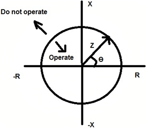
Four quadrants are necessary to understand the process. The fault impedance in the first quadrant is larger than normal since R and X are both positive. This will cause the relay to work. The relay won’t work since the angle in the second quadrant is negative. Relay operation will be the same in the third quadrant.
The restoring torque is higher than the deflecting torque in the area where the relay will not work. Furthermore, the deflecting torque exceeds the restoring torque in the operational region. Transmission lines of a small, medium, and long lengths all use distance relays.
Types of Distance Relay
The three types of distance relays are categorized as a result of how much voltage and current are compared. There are
Definitive Distance Relay
A hinge supports one end of the beam, which is positioned horizontally in this form of balance beam relay, and the other end of the beam is pulled downward by the magnetic force generated by the coil fed by the PT linked in series to the line. The torque that the descending forces produce enables the beam to reach equilibrium. The torque generated by the voltage coil acts as a restraining torque, whilst the torque generated by the current coil acts as a deflecting torque.
The contacts remain open because, under normal circumstances, restraining torque is greater than deflecting torque. The voltage of the feeder decreases, and the current value increases, in contrast, if there is a feeder problem. Impedance, which has a fixed value, is produced. Thus, the current coil pulls the beam more powerfully than the voltage coil, causing the beam to tilt in the direction of the relay contacts and trip the relay.
Time Distance Relay
Based on the relay’s distance from the problematic point, this relay automatically adjusts the operating time. This relay’s functionality is independent of the voltage to the current ratio that corresponds to that
This relay includes a current-driven component, such as an induction overcurrent relay with double winding. The spindle that supports the disc through a spiral spring is connected to the second spindle, which supports the relay contacts’ bridging component. The bridge is typically held open by an armature positioned in opposition to the pole face and activated by the circuit’s voltage to protect it.
Admittance Relay
Distance relays of this kind are used the most frequently. When used with pilot patterns, this is regarded as a tripping relay; when used with distance patterns, it is viewed as a backup relay. Because it passes across the origin in the R-X plot, this gadget has the property of being directed. The plot’s shape in the solid-state structure is representative of transmission line impedance, while it is circular in the electromechanical system.
Reactance Relay
This relay responds only to the reactance of the protected line and has a straight-line highlighted distance. It is non-directional and used as an addition to an admittance relay system, such as a tripping relay. Due to this, resistance does not affect the circuit’s overall safety. This is only used for short lines if the faulty arc resistance is of the same magnitude as the line length.
Conclusion
In conclusion, distance protection systems are frequently employed to provide primary and backup protection for AC transmission lines and distribution lines against phase-to-phase, three-phase, and phase-to-ground faults.
For more details or purchase of electrical components such as distance relays, contact us at ICRFQ. We manufacture the best electrical components in China.
If you want to find more Electronic Components Distributors, please check out the following articles:
Electronic Components Distributors In the USA
Electronic Components Distributors In UK
Electronic Components Distributors In China
Electronic Components Distributors In India
Electronic Components Distributors In Singapore
Electronic Components Distributors In Malaysia
Electronic Components Distributors In Vietnam
Electronic Components Distributors In South Korea
- The Ultimate Guide to IRFZ44N MOSFET - April 30, 2024
- AMD Ryzen 5 vs Intel i5: How to Choose the Right Processor? - April 30, 2024
- Where to buy IC chips? The Best Guide? - March 26, 2024