
Last Updated on October 24, 2023 by Kevin Chen
Transformers are electromagnetic devices that use the principle of mutual induction to transfer power from one circuit to the next. The coupling of inductances by mutual magnetic fields is known as mutual induction. A single-phase transformer, for example, has two coils, one primary and the other secondary.
Any electrical source, such as an AC generator, will feed the primary coil with power. The secondary coil receives a voltage from the primary coil’s magnetic field. This secondary coil is connected to the load and receives power as needed.
Step-up transformers are transformers used to increase the voltage to a higher level. On the other hand, step-down transformers reduce voltage to a lower level.
What is Autotransformer?
The autotransformer works on the same principle as two transformers with different windings. It operates based on Faraday’s Law of Electromagnetic Induction, which states that whenever the magnetic field and conductors are moved closer together, an electromagnetic force is induced in the conductors. Consider the transformer with two windings depicted below.
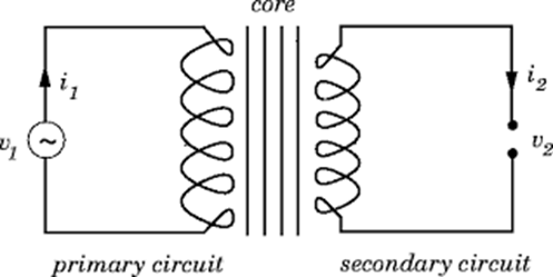
Whenever an alternating voltage is applied to the primary winding, an electromagnetic force is created due to the alternating behavior of the magnetic field formed by static conductors and AC supply. In reference to Faraday’s Law, the field and the conductors must have a relative displacement, so in this scenario, the field is alternating, and the conductors are constant. As a result, a voltage is generated in the primary winding of the transformer.
The primary winding is subjected to induced emf, which results in an alternating flux. Flux connects the transformer’s secondary winding by passing through the transformer’s core. Mutual induction is the term for this process. The secondary winding experiences an emf. The magnitude of the secondary electromagnetic force is calculated based on the number of turns on the secondary winding.
Autotransformer Working
The induced EMF equation is as follows:
E=4.44∅Nf
Both primary and secondary winding electromagnetic forces can be generalized using this formula. When we divide by the number of people, we get
E1/E2 =N1/N2 =k
The magnitude of the induced electromagnetic fields is proportional to turn, as can be seen. A step-up autotransformer is one with a higher number of turns on the secondary side. A step-down autotransformer has fewer turns than a step-up autotransformer. It’s also been discovered that flux connects the secondary winding to the transformer’s core in two-winding transformers. Between primary and secondary, there is no electrical connection. As a result, the transformer is referred to as a magnetically coupled but electrically isolated device. However, there is electrical isolation for an autotransformer. Only one winding is available. The autotransformer is thus referred to as an electrically & magnetically coupled device.
The emf induced by nature is statically induced, as shown above. Nature-induced electromotive force becomes statically induced EMF when the source alternates and the conductors are constant. The electromotive force is dynamically induced if the conductors rotate and the magnetic field is constant. The electromotive force in a transformer or autotransformer is statically induced electromotive force. Electromotive force is dynamically induced emf in the case of DC generators. Lenz’s Law determines the direction of currents for statically induced emf. Fleming’s Right-Hand Rule provides it in the case of dynamically emf. Lenz’s Law thus determines the direction of electromotive force in an autotransformer.
Energy is also transferred from primary to secondary in two winding transformers via induction, whereas in an autotransformer, power is transferred via conduction and induction. It should be noted that, according to Faraday’s Law of Electromagnetic Induction, there must be a relative change between the magnetic field and the set of conductors for induction of emf on the primary side.
As a result, on the primary side, we get AC voltage, which varies in nature. Because of the constant nature of the supply, autotransformers or two winding transformers will not operate if we provide DC. When a DC supply is provided, the primary winding will burn due to the low resistance of the primary winding.
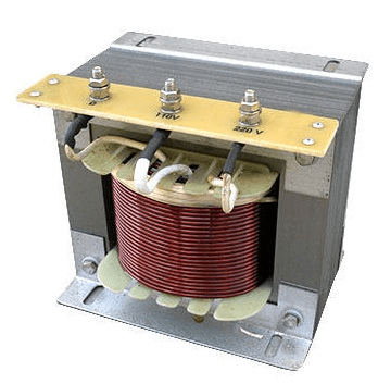
Auto Transformer Construction
A transformer consists of two parts
- Conductors
- Core
Copper is used to making the conductors in the autotransformer. They have a low resistance to the elements. Copper conductors are separated from one another by insulation. Impregnated paper, mica, and other materials are used to insulate. Eddy’s current losses can be reduced thanks to the insulation. The winding encircles the core. Compared to two winding transformers, a single winding transformer uses less copper.
The core is used to transfer flux from the primary to the secondary. Magnetic materials such as CRGO steel, silicon steel, and others make up the core. The most efficient material for the core is CRGO steel, which has the lowest hysteresis losses. The role of the core is to move flux from one part of the winding to another.
Advantages and Disadvantages of Auto Transformer.
A laminated core transformer with one winding is known as an autotransformer. It’s comparable to a two-winding transformer but with a piece of the primary and secondary winding shared by both primary and secondary sides. So, to better comprehend this topic, this article discusses the benefits and drawbacks of using an autotransformer starter.
Advantages Of Autotransformer.
- The motor’s current is more than the supply’s current.
- It is less costly.
- For long startup periods, this method works well.
- The autotransformer’s starting voltage can be modified by selecting the relevant tap.
- The circuit has advantages over beginning with a standard autotransformer, which must be entirely detached at some point during the start, causing high voltage impulses that might damage the stator’s electrical insulation.
- The autotransformer starter considerably reduces the inrush current.
- It’s for big motors that can’t be started by connecting to the network directly. Large motors, especially those with a substantial load, cannot be started with the star delta stater.
- The autotransformer starter considerably reduces the inrush current.
Disadvantages of Auto Transformer
- One of the most significant downsides of the autotransformer, which is why it is not widely used, is that the primary winding and secondary winding are not insulated from each other.
- When the secondary winding of an autotransformer intended to produce high voltage and low voltage from breaks, the entire primary voltage is transferred to the secondary terminal, putting the user and the equipment in danger. As a result, the autotransformer should not be used to connect high and low-voltage systems.
- They are only utilized in a few situations where a slight voltage difference between output and input is required.
- The primary and secondary windings have a small leakage flux; hence the impedance is low. This causes significant short circuit currents in fault circumstances.
- A significant incident can negate the initial cost savings if the tapping range is extremely significant.
Autotransformers: Additional Information
Autotransformer Features
For larger kilowatt motors, autotransformer starter ratings are lower than conventional motor starter rates. Because the size of an autotransformer is so tiny, cost-effective materials will be used. Because the copper and iron losses are reduced by effectively lowering the material, auto transformers have a higher efficiency than standard isolation transformers.
Autotransformer Protection
Transformer standard Auto transformer protection is also possible using differential protection relays and accessories. Transformer differential protection has a variety of additional purposes (mapping to transformation ratio and vector group, stabilization (restriction) against inrush currents and over excitation) that necessitate specific primary considerations in terms of configuration and setting settings.
The relay’s other functionalities can be put to good use. However, for reasons of hardware redundancy, backup protection capabilities must be implemented in separate hardware (another relay).
As a result, the differential protection over current-time protection can only be employed as a backup against external problems in the associated power supply. The transformer’s backup protection must be distinct from the current relay. As a temporary short-circuit protection, the Buchholz protection is used.
Different forms of differential protection strategies for auto-transformers have been presented. The availability of the major CTs in a particular installation determines which scheme will be employed.
In addition to the usual differential protection scheme, it is recommended that a differential protection scheme that is sensitive to faults around the common winding star point be used. Another option is to merge two separate schemes, each with its attributes.
Autotransformer Tertiary Winding Protection
The differential protection method for standard isolation transformers and autotransformers is the same from the standpoint of differential relays. The sole distinction is that the relay has access to all three independent currents within the tertiary delta winding.
As a result, the tertiary delta winding can be loaded with this configuration. The used equation and the benefits of such a differential scheme can be easily calculated and executed. A tertiary delta winding is utilized in autotransformers.
It’s utilized to prevent harmonic voltages from being generated due to magnetizing currents impacting the lower zero sequence impedance. The secondary delta winding is rated at one-third of the auto transformer’s rated throughput power. It reroutes the current flow that has been detected due to the fault. It also lowers the amount of unbalancing in three-phase loads.
Conclusion
This is about an overview of autotransformers, including how they function, how they’re built, and their benefits and drawbacks. Autotransformers are used to start induction motors and for laboratory reasons. They have a 98 percent efficiency. They are challenging for application, require less maintenance, and have a longer lifespan.
For more details or purchase of autotransformers or any other electrical component, contact us at ICRFQ. We manufacture the best electrical components in China.
If you want to find more Electronic Components Distributors, please check out the following articles:
Electronic Components Distributors In the USA
Electronic Components Distributors In UK
Electronic Components Distributors In China
Electronic Components Distributors In India
Electronic Components Distributors In Singapore
Electronic Components Distributors In Malaysia
Electronic Components Distributors In Vietnam
Electronic Components Distributors In South Korea
- Where to buy IC chips? The Best Guide? - March 26, 2024
- Breaking Down Barriers: Overcoming Obstacles in Cross-Border Electronic Component Trade - March 4, 2024
- Everything You Need to Know About Amplifier IC Chips - March 4, 2024


