
Last Updated on October 22, 2023 by Kevin Chen
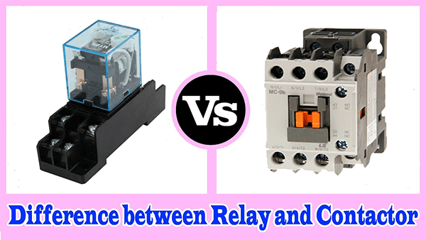
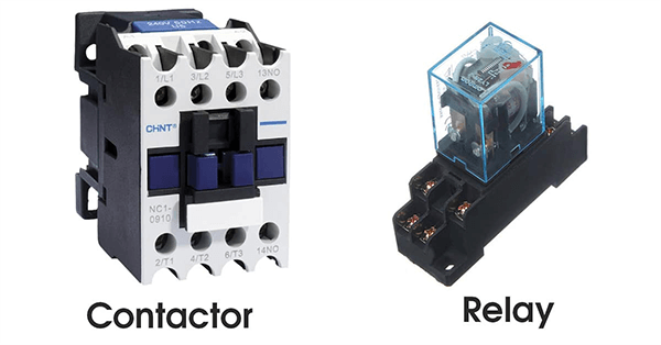
Both relays and contactors are electromagnetic switches used to switch and control actions. The primary distinction between relays and contactors is their load type and the power utilization factor.
Relays are typically used in low-voltage or high-current applications. On the other hand, contactors have relatively high rated voltage and current values. Relays and contactors are switches that use electricity to switch loads and control circuits. Relays typically have a load current rating of around 20A, whereas contactors can support loads of up to 30, 40, or 50A.
What Is Relay
Relays are electrically operated switches used to regulate circuits by sending low-power signals. It serves as a connection between the circuit to be regulated and the circuits that govern it. Electrical isolation between the controlling and controlled circuits is maintained with the usage of relays.
A relay has two sides, primary and secondary, and operates in this manner. A coil is powered by the control signal, a low-power dc supply on the primary side. The load that needs to be regulated is connected to the secondary side: a typical fan, pump, bulb, compressor, or other AC load.
A magnetic field is generated when a current travels through an electromagnetic coil. An armature is attached to the end of the coil with the help of a spring. When the supply energizes the coil, the armature is attracted to it. The armature returns to its usual position after the coil is de-energized. As a result, the circuit is completed, and the load receives and responds to the supplied electrical energy.
What Is Contactor
A contactor is an electrical device meant to turn on or off an electrical switch. Contactors with heavy-duty contacts are used to manage power-consuming devices and ensure safe power circuit switching.
After being activated by an AC source, contactors are controlled by the coil (solenoid), similar to how relays work. However, unlike relays, it incorporates an arc suppressing cover that provides quenching to the arc created by the load while the contacts are open. The moving contact connects with the stationary contact due to the armature’s upward attraction in contactors. However, the falling out of the armature disconnects the moving and stationary contacts following de-energization.
In the open state of the magnet (armature), there is a considerable air gap, resulting in low reactance. When the coil is energized, it pulls a considerable amount of current, closing the armature and reducing the air gap. This raises the reactance while lowering the coil current. In this scenario, the coil current lowers to magnetizing current, keeping the contactor closed against the spring’s force.
What Is the Difference Between a Contactor and a Relay?
You might be wondering what the primary distinctions are between a relay and a contactor now that you know how they work. The fundamental difference between the two devices is the electrical current rating designed to withstand. Because contactors are used to manage electrical loads with high voltage and current, they differ from standard relays in a few ways.
Read the feature definitions below to learn more about the differences between the two devices. They explain how the instrument works and what it’s for.
Load Rating
The load ratings on both the relay and the contactor are different. Their load rating is linked to their present rating. Low-power circuits having a maximum current rating of 10A or less are suitable for the relay. The contactor is designed for high-current circuits with 10 amps or a higher current rating.
Contacts
Both the NO and NC contacts of a relay and a contactor are the same, but the circuit determines the use they are controlling. A relay is commonly utilized for many applications for both NO and NC. The coil can be reconnected even if it is not powered. The purpose of the relay determines whether it is NO or NC.
NO contact is frequently used with a contactor (form a contact). When the coil is not electrified, the circuit connection is broken. When the coil is not electrified, the contactor has most NO contacts to disconnect the circuit.
Auxiliary Contacts
Auxiliary contacts are utilized to give a secondary point of contact for the primary contact. It’s used to add more NO or NC contacts to a sequence for a certain procedure. Because a single relay has many NO and NC combinations, it does not have auxiliary connections. We can create sophisticated commands out of any combination.
Auxiliary contacts, such as NO or NC, are commonly found on contactors and serve a different purpose in the circuit. This auxiliary contact, for example, controls the break or start motor while the main contact supplies electricity to the motor.
Safety Plan
The relay and contactor safety plan is critical for protecting the circuit in a catastrophic event, such as overloads, voltage, or current in the circuit exceeding the limit or broken components. Because relays are used for low-voltage circuits and have a spring that pulls the contact when the coil is not activated, safety plans are unnecessary.
On the other hand, contactors are employed in high-power circuits; therefore, safety procedures are required. When the coil is de-energized, spring-loaded contacts are frequently used to cut the circuit. It is dangerous if the circuit is activated while it should be off.
Arc Suppression
When a high-power circuit is energized or de-powered, sparks are common. Arc suppression is a technique for suppressing arcs by lengthening the arc travel route. Low-power circuit relays do not emit large sparks, if any at all. On the other hand, contactors are used in high-power circuits and emit sparks when they switch contacts.
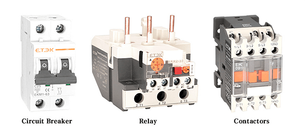
Overload Safety Plan
When a circuit’s load exceeds the limit, an overload safety plan is implemented to prevent damage and protect the circuit. Overload events are rare in relays; hence overload safety precautions are rarely used.
If the current exceeds the maximum current rating for a length of time, contactors are linked to overload, which will destroy the circuit (10-30 seconds). When the current is too strong, it protects the equipment.
Size
Relay and contactor physical sizes are determined by their components. A relay’s total size is smaller than that of a contactor since its components are smaller. Because a contactor has more components, it has a larger overall size than a relay.
Switching Speed
For controlling circuits, switching speed is critical; even a fraction of a second is required to connect or disconnect the current route. Contacts can be switched significantly faster using a relay than with a contactor. Contactors are substantially faster than relays at switching contacts.
Connection
In addition to the NO and NC connections, the relay and contactor are connected to different locations for specialized purposes. The relay uses a common contact to connect to the neutral point. If the power exceeds the limit, the overload is connected to the contactor, interrupting the circuit.
Power Consumption
We must first calculate the power consumption of relay and contactor control circuits to ensure that they can be operated efficiently. The electromagnet components of the relay are tiny and consume less electricity. Large electromagnet components in the contactor demand more electricity.
Application and Voltage Rating
Both the relay and the contactor have a maximum voltage rating, similar to the load rating. This will assist us in deciding whether to utilize a relay or a contactor, allowing us to select the optimum option. Single-phase circuits are where relays are most commonly employed. Relays with a rating of up to 250 volts are common. Three-phase circuits are where contactors are most commonly employed. Contactors with a rating of up to 1000 volts are routinely used.
Functions
Both relay and contactor perform various duties due to load rating, voltage rating, and switching speed. Signal transmission, conversion, control and automation circuits, protection and small switching electronic circuits, and detection are common relays applications.
The circuit’s operational current is minimal. It is widely used in circuits to control low signals. The contactor is primarily used to connect or disconnect the main circuit with a higher current than the control and switching power circuits (transformer, motor starter, capacitor bank).
Cost
One of the most important factors to consider when building a control circuit is cost. We don’t want to create a circuit with wasteful components. It is self-evident that relay is less expensive. The expense of a contactor is higher.
Applications of Relay and Contactors
Contactor vs. Relay applications are typically differentiated by the amount of electricity the switch is designed to handle; relays are typically used in low-power or single-phase circuits, while contactors are typically used in high-power circuits. (single-phase as well as a three-phase circuit)
Relays are used to route signals, switch currents, and in some cases, act as a form of logic. While solid-state components can perform switching and routing functions, the relay has the advantages of low closed-circuit resistance, resistance to reverse current flow from inductive loads, and the ability to act as an isolated control transition between the low- and high-voltage circuits.
Contactors are motor control devices that come in two poles for DC and three and four poles for AC applications, such as electric motor control, switching electric heating elements, and big banks of lights.
How to Choose A Contactor or A Relay?
If you’re having trouble deciding whether to utilize a contactor or a relay, consider the following suggestions:
Control relays are ideally suited for single-phase circuits with a minimum electrical capacity of 250 VAC and a current capacity of 10 A. Alternatively, contactors may be used in a single to a three-phase electrical circuit with a 1000 VAC or greater electrical capacity needed when the current capacity is 9A or above.
It will be easier to decide which of the two devices best suits your needs once you have considered these crucial considerations. Because both devices have specific and individual tasks, it’s essential to utilize the right one for the right situation, as previously said.
Contactor VS Relay Failure
Relay failures
There are three basic reasons why relays fail: The relay coil wire or connections have an open circuit (break) or excessive resistance, resulting in little or no current flow through the coil. The relay will not turn on as a result of this. Electrical equipment supplied with power through the typically open contacts of a relay does not operate due to this failure.
When the contacts are closed, they are scorched or otherwise damaged, resulting in a high degree of series resistance with the load device. The closed relay contacts may experience minimal or no current flow. Electrical equipment provided current through the typically open relay contacts do not operate erratically due to this failure.
They typically have open relay contacts welded or jammed closed (energized). SPDT relays result in the typically open contacts remaining closed even after the relay coil has been de-energized and the normally closed contacts remaining open at all times.
The relay may be conducting too much current or switching at too high a voltage, causing this difficulty. When the relay coil is not electrified, this failure causes electrical devices connected to the typically open contacts of the relay to operate.
Contactor failure
The most typical reasons for contactor failure are:
1.High Current
2.Electrodynamic Forces During A Short Circuit
3.Overvoltage, Constant Chattering
4.Aging Temperature, Power Quality
5.Corrosive Environment
6.Voltage and Frequency Fluctuation
7.Mechanical Stress.
Last but not least
To switch a motor, lighting fixture, or any other equipment that is known to consume large amounts of electricity, you should utilize a contactor—at least one specific pair of contacts in a three-phase input-output capacity. The contacts are open and, in certain situations, divided into different groups, such as the auxiliary contact with NO and NC capacities.
In contrast, relays will only have one or two pairs of open or closed contacts. By just twisting the coil, you can open or close the contact. Because these devices perform different purposes, it’s ideal to utilize them only when needed.
Conclusion
As a result, we can state that relays are designed for single-phase applications and are utilized in automation and protection circuits such as motor control, electric pumps, and other similar applications. Contactors are useful in induction motors, transformers, capacitor banks, and other three-phase applications.
Lastly, if you are planning to purchase any electrical component, contact ICRFQ, we are the best electrical components manufacturer in China.
If you want to find more Electronic Components Distributors, please check out the following articles:
Electronic Components Distributors In the USA
Electronic Components Distributors In UK
Electronic Components Distributors In China
Electronic Components Distributors In India
Electronic Components Distributors In Singapore
Electronic Components Distributors In Malaysia
Electronic Components Distributors In Vietnam
Electronic Components Distributors In South Korea
- Where to buy IC chips? The Best Guide? - March 26, 2024
- Breaking Down Barriers: Overcoming Obstacles in Cross-Border Electronic Component Trade - March 4, 2024
- Everything You Need to Know About Amplifier IC Chips - March 4, 2024


