
Last Updated on October 27, 2023 by Kevin Chen
An integrated circuit is a circuit made up of inseparable components that are electrically coupled together in a way that prevents the IC from being detached for construction or commercial purposes. Such a circuit may be constructed using a variety of technologies. A monolithic integrated circuit is what is currently referred to as an IC. Kilby is thought to have invented the first functional integrated circuit in 1958, and in 2000, he was awarded the Nobel Prize in Physics for his efforts. The US Air Force was the product’s initial purchaser. This post talks about The Integrated Circuit Design Techniques You Should Know.
Integrated Circuit Design Techniques.
We need to design massive, complicated processors quickly to take advantage of the flood of transistors that Moore’s Law has given us. Complexity is a barrier to having huge chips function properly; many good chip ideas have been buried in the sea of minutiae that must be resolved before the chip can work. Integrated circuit design is challenging because engineers must balance a variety of issues:
Various Degrees Of Abstraction
It takes many layers of detail to refine an idea for an IC. The designer must start with a specification for the chip’s function, expand the function into an architecture, then expand the architecture into a logic design, and finally expand the logic design into a layout.
Multiple And Conflicting Costs
The designer must not only sketch a design through numerous levels of detail but also consider costs—not monetary charges but rather standards by which the design quality is assessed. The chip’s operating speed is one crucial cost. Two architectures can work at substantially different rates when performing the same task (like multiplying, for example). We will see that chip area is another crucial design cost because chips larger than 1 cm2 cannot be made at all, and the cost of manufacturing a chip is exponentially linked to its area. Furthermore, many design choices will improve one cost statistic at the expense of the other if several cost criteria, such as area and speed requirements, must be met. The practice of balancing opposing limitations drives design.
Short Design Time
A designer would have time to consider how a design choice might affect the final product in a perfect world. However, the world in which we live is not perfect. If chips are released too late, their sales may be marginal or nonexistent due to market share theft by rivals. Designers are, therefore, under pressure to create chips as soon as feasible. To develop a concept into a functional ASIC, only a few weeks may be available in the case of application-specific IC design.
Design abstraction and hierarchical design are two strategies designers have created to eliminate extraneous details. Designers also extensively use computer-aided design technologies to evaluate and synthesize the design.
Hierarchical Design
Components
Chip designers can divide and conquer by decomposing the chip into a hierarchy of components. As seen in the diagram below, a part comprises a body and several pins; the full adder contains pins a, b, cin, cout, and sum. We can create numerous instances of this type if we take this full adder as the specification. It is often helpful to repeat frequently used parts, for example, when creating an n-bit adder from n-full adders.
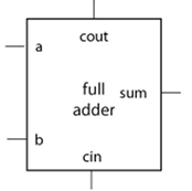
Usually, we name every instance of a component. We refer to the pins on a certain part by giving the component instance name and pin name together because all components of the same type have the same pins; it’s typical to separate the instance and pin names by a dot. We can think of add1.sum and add2.sum as separate terminals if we have two full adders, add1 and add2 (where a terminal is a component-pin pair).
Design Abstraction
Levels of modelling
Design abstraction is essential to the development of hardware systems. To oversee the design process and ensure they achieve key design objectives like speed and power consumption, hardware designers employ a variety of layers of design abstraction. The logic gate is the most basic illustration of design abstraction. The nonlinear circuit used to construct a gate is streamlined into a logic gate, which only accepts binary Boolean values. Several design chores, such as an accurate delay calculation, become difficult or impossible when expressed in terms of logic gates. Other design activities, such as logic optimization, are too laborious to be carried out on the circuit. We select the design abstraction that fits the design task the best.
Higher abstractions may also be used to refine initial decisions using more precise models. For instance, we frequently optimize logic using straightforward delay calculations before refining the logic design using precise circuit data. Hierarchical structure and design abstraction are not the same. An architecture made of Boolean logic functions, for instance, uses components at the same degree of abstraction as those used in a design hierarchy. Each level of the order increases complexity by introducing more components. As it is recast to a lower level of abstraction, the number of components might not change; the complexity is increased by the more complex behaviour of those components.
Top-down and bottom-up design
Design always necessitates ascending from the least abstract description and descending from the top of the abstraction hierarchy. Adding useful information to the abstraction must be the first step in the design process. Top-down design choices, however, are made with little knowledge of the alternatives available at each level of abstraction. We want to select the candidate that best satisfies our speed, area, and power needs.
We cannot estimate such expenses accurately until we have an early design. Bottom-up analysis and design propagate cost information up to higher levels of abstraction; for example, we might redesign the logic using more precise delay information from the circuit design. Before you finish the implementation, the experience will assist you in estimating expenses, but most designs call for cycles of top-down design followed by bottom-up redesign.
Computer-Aided Design
Cad Tools
Given performance and design time limits, automation of the design process utilizing computer-aided design (CAD) tools that automate portions of the design process is the only practical approach to creating chips. When done effectively, using computers to automate design aids in resolving all three issues:
Computer programs can analyze cost trade-offs more effectively than humans because they are more methodical and work much more quickly than humans when given a well-defined task. Dealing with multiple levels of abstraction is easier when you are not engrossed in the specifics of a particular design step.
Design Entry
By the design task they manage, computer-aided design tools can be grouped. The simplest CAD tool contains design entries, such as an interactive schematic sketching software. Although they frequently make it easier to modify a design, design entry tools don’t perform any design work; rather, they capture a design in machine-readable form for other programs.
Analysis And Verification
Tools for analysis and verification are more potent. The differential equations governing how the circuit reacts to an input waveform over time are solved, for instance, by the Spice circuit simulator. Although many analytical jobs are too challenging to complete manually, such a tool does not instruct us to alter the circuit to make it behave as we like.
Synthesis
Synthesis tools take a higher-level description and turn it into a design at a lower degree of abstraction. Some algorithms for layout synthesis can create a layout from a circuit description.
Computer-aided design is not a cure-all. Marketing brochures cannot be converted into finished IC designs, nor are they anticipated to be able to do so in the future. Designers will always be required to develop innovative designs and complete design jobs that are too nuanced for algorithms to handle.
The most potent synthesis and analysis tools work with a somewhat constrained design model; therefore, hierarchical design and design abstraction are equally crucial to CAD tools as they are to people. While CAD tools can be beneficial in some aspects of the design process, algorithms that have the in-depth understanding needed to address a single design challenge frequently lack the breadth of information necessary to balance several requirements.
Tools As Aids
To be most useful, CAD tools must be used carefully by a human designer. However, because they are the only means of handling the complexity involved in designing massive integrated circuits, CAD tools are a crucial component of the future of IC design. The number of choices when designing a manual chip with 100,000 or even 100 million transistors overwhelms the designer. Not every option is equally significant; some might slightly alter the size and speed of the chip, while others might significantly change its price.
By focusing on the wrong choices, a designer risks creating issues that are difficult to fix after the fact. By automating specific design steps, CAD tools enable designers to quickly dispense with unimportant choices and focus on the chip’s crucial issues.
Long lines, for instance, may cause excessive delay, use more power, and expose devices to crosstalk. However, when designing a device manually, it may be simple to miss this single connection, and the fault will not be discovered until the chip returns from fabrication. When studying complex scenarios where the answer to one issue leads to the production of another, such as when shortening one wire results in the lengthening of other wires, CAD tools are essential. Such problems can be found using a computer that analyzes delays through the chip. Problems may not have straightforward answers when two restrictions compete.
For instance, speeding up one design component can make another part excessively bulky and slow. With analytical ways to assess the cost of options and synthesis methods that allow us to develop a candidate solution to a problem swiftly, CAD tools assist us in resolving these issues. Designing systems to satisfy multiple costs necessitates the evaluation of candidate designs because a complete system cannot be optimized by simply improving the performance of each component. Making a chip’s part run as quickly as possible in isolation does not guarantee that the chip will operate as soon as possible. By using CAD tools to suggest and analyze solutions, we can study far larger problems than we could by hand.
Conclusion
Thanks for reading. If you like this article, please explore the rest of our website for more great content like this one and learn more. If you have any questions about this article, please leave them in the comment section below, and we will do our best to respond to them.
If you need information or want to order IC, contact us here at ICRFQ, your leading electronic components in china, and we will ensure you get the best product at the best price.
If you want to find more Electronic Components Distributors, please check out the following articles:
Electronic Components Distributors In the USA
Electronic Components Distributors In UK
Electronic Components Distributors In China
Electronic Components Distributors In India
Electronic Components Distributors In Singapore
Electronic Components Distributors In Malaysia
Electronic Components Distributors In Vietnam
Electronic Components Distributors In South Korea
- Where to buy IC chips? The Best Guide? - March 26, 2024
- Breaking Down Barriers: Overcoming Obstacles in Cross-Border Electronic Component Trade - March 4, 2024
- Everything You Need to Know About Amplifier IC Chips - March 4, 2024


