
Last Updated on October 22, 2023 by Kevin Chen
Every day, we all witness things in life that we have no idea what are. You probably wouldn’t be able to explain what a ferrite bead is if you heard the term, but these beads are an essential element of our everyday electronics.
So, what exactly is a ferrite bead, and how does it function?
What are Ferrite Beads
Ferrite beads are used in electrical circuits to decrease or eliminate electromagnetic interference (EMI) and high-frequency noise. They may be referred to as ferrite sleeves, chokes, blocks, filters, cores, or rings, but they all serve the same purpose regardless of language.
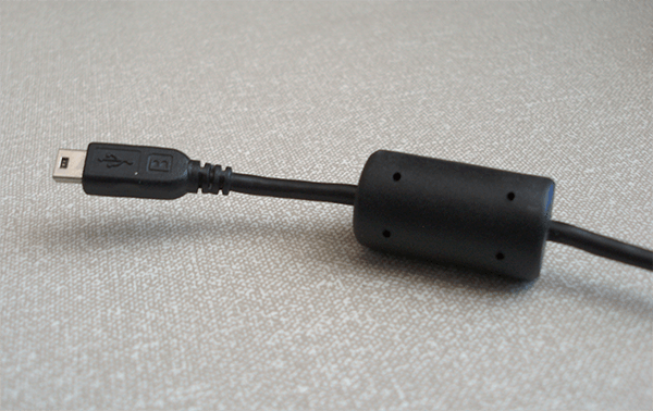
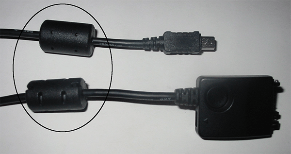
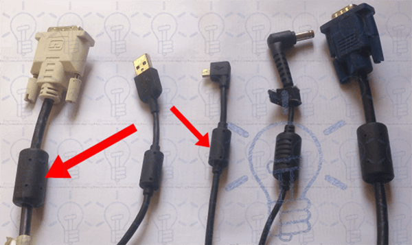
Whether you realize it or not, you’ve probably seen ferrite bands in operation regularly. They’re most typically found in the huge plastic cylinder on exterior cablings, such as connecting wires and charging cables. Smaller ferrite beads are still utilized inside circuits like transistors and integrated circuits.
They are the simplest and most affordable ways to minimize unwanted high-frequency noise and interference. They are frequently employed in a wide range of electronic devices.
How do Ferrite Beads work?
While ferrite beads are commonly thought of as an inductor since they absorb EMI, they can also function as a capacitor, inductor, and resistor in tandem. On the other hand, the inductor is the principal source of EMI attenuation.
Ferrite beads block EMI from a device and from a device to a device. They work as a passive low-pass filter that transforms radio frequency (RF) energy to heat by obstructing the flow of high-frequency signals with a coiled wire over the bead. By reflecting undesirable energy up the wire or releasing it as heat, this decreases the detrimental effects of EMI and RFI.
This distinguishes them from a pure inductor, which does not dissipate energy but instead produces reactance obstructing EMI flow.
The Origins of Ferrite Beads
To clear up the initial misunderstanding, ferrite beads are not beads. They’re mini-inductors. A toroid is an object that people refer to as a bead. (A toroid is an insulated coil or enameled wire wound on a powdered iron doughnut form.) It’s utilized in electronic circuits as inductors, especially when huge inductances are required at low frequencies. They’ve been used as transformer cores for millennia). Ferrite inductors will be referred to as ferrite beads to preserve uniformity with the rest of the industry.
Like other surface-mount components like resistors and capacitors, Ferrite beads are surface-mount components. They’re also available in the exact sizes as the other parts.
Ferrite beads are made of a ferrimagnetic substance known as ferrite in terms of composition. This material functions similarly to a wire coil inductor. It has a reasonably high inductance in a tiny form factor, appealing.
These components are typically defined by their impedance at a specific frequency rather than their inductance. The impedance of a ferrite bead, like an inductor, varies with frequency, with low impedance at low frequencies, rising to a high point, and then dropping off.
What are Ferrite Beads Used For?
Ferrite bead inductors reduce high-frequency signals in electronic components because their impedance is inductive. When a ferrite bead choke is installed on the power line to electronic equipment, it eliminates any high-frequency noise that may be present on the connection or output from a DC power supply. Noise suppression can be achieved in various ways, including a ferrite clamp or a switched-mode power supply. Using ferrite beads as a ferrite filter suppresses and eliminates transmitted EMI.
An EMI filter bead/power supply filter is usually rated for a specified DC threshold among the different uses of ferrite beads as filters. The component may be damaged if the current exceeds the specified value. The problem is that heat has a significant impact on this limit. The rated current rapidly drops as the temperature rises. The impedance of the ferrite is also affected by the rated current. A ferrite bead will “saturate” and lose inductance as DC increases. Saturation can reduce the ferrite bead impedance by up to 90% at reasonably high currents.
Ferrite Bead vs. Inductor
Although a ferrite bead can be treated as an inductor, ferrite bead inductors are not typical inductors. If you want to compare the behavior of a ferrite bead to that of an inductor, you can send an analog signal through the bead and sweep the frequency up and down several orders of magnitude. When you plot the frequency-swept measurements for a ferrite bead against an inductor with identical low-frequency behavior, you’ll notice that the ferrite bead has a steeper roll-off at higher frequencies.
With this RLC network coupled with a series resistor, a ferrite bead can be described as capacitors, inductors, and a resistor in parallel. The series resistor measures how resistant the gadget is to DC currents. In this form, the inductor is a ferrite bead whose primary role is to attenuate high-frequency signals by producing inductive impedance via Faraday’s Law. The parallel resistor in this model accounts for eddy currents induced within the ferrite bead at high frequencies. Finally, the capacitor in this model compensates for the parasitic capacitance of the component.
The predominantly resistive impedance in only a tiny band of a ferrite bead impedance curve is relatively high. Within this small region, the bead’s inductance reigns supreme. The ferrite bead impedance appears capacitive across higher frequencies, and the impedance rapidly drops. The capacitive impedance falls to zero as the frequency rises, and the ferrite bead impedance seems resistive.
Different Types of Ferrite Beads
Based on the construction, these are divided into two categories. They are, indeed.
Wire-wound Ferrite Bead
These are used to reduce the magnitude of frequencies over a wide range. This type of bead has a lower DCR and a more excellent current rating (DC resistance).
Chip Ferrite Bead
This is a conventional type with a limited frequency range and attenuation. If they operate above a particular DC, they will be damaged. That is, as the temperature rises, the present rate value lowers. As a result, heat will have an impact on its performance.
A high-frequency bead is an electronic component that eliminates high-frequency noise energy over a wide frequency range. It absorbs noise energy and dissipates it as heat, making it more resistant to noise over the appropriate frequency range. The high-frequency type of winding type inductor functions as a high pass filter. Below is the IEEE symbol for ferrite beads.
As shown below, the ferrite bead’s equivalent circuit consists of a series connection of an inductor and a resistor.
Ferrite Bead Inductance
The electronic circuit’s frequency range primarily determines the inductance of this bead. This functions as an RF suppressor when wrapped around the power supply wire. It has a low impedance at low frequencies. It has a high impedance at high frequencies. The electronic component’s electromagnetic interference (EMI) and radio frequency interference (RFI) noise can be reduced at high frequencies.
Simplified Ferrite Bead Modeling and Simulation
A simple circuit comprising resistors, inductors, and capacitors can represent a ferrite bead. The three most frequent forms of ferrite beads are inductive, resistive, and capacitive reactions.
You should use the bead in the circuit’s resistive region to filter high-frequency noise, such as EMI filtering. The gadget acts as a resistor, absorbing and dispersing high-frequency noise as heat.
DC Bias Current
When choosing a ferrite bead filter for high-power applications, consider the filter bandwidth and the component’s impedance qualities in terms of DC bias current. Remember that the load current through a ferrite bead is never zero in a power supply filtering application. Additionally, as the DC bias current increases from zero, these characteristics change significantly. Saturation of the core material begins with an increase in DC bias current, lowering the inductance of the bead significantly.
LC Circuit Resonance
You should think about resonance peaking when developing a ferrite beads system. When the noise-filtering circuit includes a decoupling capacitor, this phenomenon happens. Ignoring the effect could have unfavorable consequences, such as exacerbating rather than reducing the ripple and noise energy problem in your circuit. The regular DC/DC conversion switching frequency is where resonant peaking occurs.
Resonance Damping Methods
There are various strategies to reduce resonant peaking in your circuit dramatically. Incorporating a series resistor in the decoupling capacitor circuit is one method. While this strategy minimizes system resonance, it compromises high-frequency bypass performance. A small parallel resistor might be added across the ferrite bead filter as an alternative; however, this design reduces the device’s attenuation efficiency at high frequencies.
A big capacitor (CDAMP) and a series damping resistor are typically used to achieve the best resonance damping results (RDAMP). When combining the two components in your noise-filtering circuit, you may reduce resonant peaking while maintaining bypass performance, even at high frequencies.
Ferrite Bead Selection Guide
Now that you’ve mastered the ferrite principle, it’s time to choose one for your gadget. This is not difficult, and you must pay attention to a bead’s specifications if you want to know how to select a ferrite bead for a project. Are ferrite beads required for my design, you might wonder? The answer is not straightforward, as with many technical decisions. A ferrite bead may be the perfect solution for your design if you know your board will be subjected to conducted EMI over a specific frequency range, and you need to attenuate these frequencies.
It is natural to conclude that ferrite beads “attenuate high frequencies” based on their inductive action without more analysis. On the other hand, Ferrite beads can only help attenuate a restricted range of frequencies; therefore, they can’t be used as a broad low-pass filter. You must select a ferrite bead with a resistance band in which your unwanted frequencies fall. The bead will not have the desired impact if you go too low or too high.
Before choosing a ferrite bead for your project, check whether the manufacturer can give impedance vs. load current curves for the ferrite bead. If you’re confused about selecting a ferrite bead, this is by far the best tool you can use. You’ll need a ferrite bead that can take highly high load currents without saturating and losing impedance within the allowed frequency range if your load currents are high.
Ferrite bead in Power Supply
A bypass capacitor must be added to any electronic circuit when the bead in the power supply line is used. At low frequencies, these act as inductors, opposing current changes. For example, if an IC draws a burst of current, the bead will resist the surge, potentially obstructing the circuit’s operation.
A bypass capacitor is required to hold the charge and provide such power surges. High frequencies will be filtered after connecting the capacitor and the ferrite bead. The use of ferrite bead inductors has the advantage of producing steeper roll-off characteristics at low frequencies and providing inherent resistance with LC resonance frequency dampening.
Cautions
A bypass capacitor is required to hold the charge and provide such power surges. High frequencies will be filtered after connecting the capacitor and the ferrite bead. The use of ferrite bead inductors has the advantage of producing steeper roll-off characteristics at low frequencies and providing inherent resistance with LC resonance frequency dampening.
Voltage drop wasn’t a serious concern in the days of higher voltage circuits. We have a bunch of low-power circuits that can work with voltages as low as 2 volts. You can’t afford to lose much at those levels. Ferrite beads provide a DC voltage drop in your circuit. It may not appear to be much, but if your integrated circuits (ICs) have a short high-current draw condition, the loss can add up quickly. Make sure your ferrite beads aren’t causing any voltage drops.
Because ferrite materials are resistant at high frequencies, the absorbed energy is mostly dissipated as heat. When a ferrite choke is used on a power supply line, this heat isn’t necessarily a problem for your PCB, but it can be if it’s utilized to dissipate high frequencies at high currents. This heat could become an issue if your system is particularly noisy, and the bead will absorb many high frequencies. Make sure to account for the heat dissipation of the bead.
Ferrite beads can be valuable, but only if you fully comprehend how they function. Keep in mind that they only attenuate signals in a specific range, and their efficiency is influenced by temperature and load current. To get the most out of a ferrite bead, ensure it fulfills your exact requirements. Then, when putting the bead, remember to account for voltage drop and heat.
Conclusion
If you’re trying to figure out which ferrite band to use in your circuit, keep in mind that beads don’t work as a wide band low-pass filter because they only stop a specific range of frequencies. The ferrite band you select must have the appropriate resistive band to block unwanted frequencies. Unwanted EMI will not be reduced by a resistive band that is too high or too low.
Thus, if you plan to purchase ferrite beads, contact us as ICRFQ; we are the best electrical components manufacturers in China.
If you want to find more Electronic Components Distributors, please check out the following articles:
Electronic Components Distributors In the USA
Electronic Components Distributors In UK
Electronic Components Distributors In China
Electronic Components Distributors In India
Electronic Components Distributors In Singapore
Electronic Components Distributors In Malaysia
Electronic Components Distributors In Vietnam
Electronic Components Distributors In South Korea
- Where to buy IC chips? The Best Guide? - March 26, 2024
- Breaking Down Barriers: Overcoming Obstacles in Cross-Border Electronic Component Trade - March 4, 2024
- Everything You Need to Know About Amplifier IC Chips - March 4, 2024


