
Last Updated on April 10, 2022 by Kevin Chen
What comes into your mind when you hear the word ‘instrument?’ The first thing that you will think of is the measurements. This is because most instruments are used for measuring the value of something.
When it comes to transformers, you need to know that they are used in almost all electrical devices and electric instruments.
They don’t just affect how much power goes through an appliance; they also affect the voltage and current, which ultimately affects the performance of the appliance. You should be able to use a single transformer on several devices.
But if your appliances require different voltages or currents, then you will need a different transformer for each one. This blog post will tell you everything you need to know about instrument transformers.
What is an instrument transformer?
An instrument transformer is a type of transformer that is used to measure the electrical value or quantities. The most common parameters that are measured by instrument transformers include current, voltage, power, energy, power factor.
Well, the most basic function of an instrument transformer is to step down the AC voltage and current. Usually, the current and voltage of power systems are high. There must be a solution to cut down these electrical data and this is where an instrument transformer comes in.
They are also used in several electrical appliances such as lamps, motors, and other devices. They have a very important role in the measurement of AC voltage, current, and power. This key feature is the force behind their massive popularity worldwide.
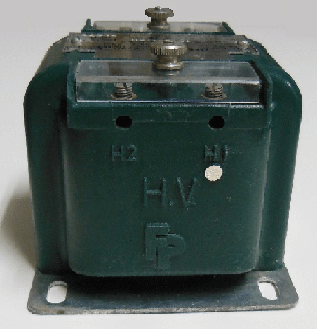
The construction of instrument transformers
What does an instrument transformer look like, or, how is it constructed? If you know the basics of any typical transformer, expect the same with this instrument transformer. The parts and components are almost the same.
The main parts of an instrument transformer include primary coil, secondary coil, core, iron core, and clips.
An instrument transformer can be made to work at different frequencies by choosing the appropriate core material for the instrument transformer. For example, using silicon steel for high-frequency transformers is usually preferred over cast iron cores as it is much lighter to carry around.
The primary coil will be connected to the circuit or device that needs to be measured while the secondary coil will measure and indicate the value on an instrument panel or meter connected to it.
Clips are used to connect wires from one part of the circuit to the other. They serve as a means of electrical connection between wires and protect from short-circuiting.
The “primary coil” is the coil that is connected to the circuit under test. The “secondary coil” is attached to an instrument panel or meter that indicates the value being measured by the instrument transformer.
A typical voltage transformer will have a primary voltage rating of 120 Volts, while its secondary voltage rating is 240 Volts, indicating that it can step down 120 volts (from a line) and increase it to 240 volts (to feed an appliance).
In contrast, a typical current transformer will have a primary current rating of 15 Amps, while its secondary current rating may be as high as 150 Amps, indicating that it can step up 15 amps (from a line) and reduce it to 150 amps (to feed an appliance).
An instrument transformer may also have multiple coils, each of which has its function. For example, a three-coil instrument transformer may have three separate secondary coils, each of which is attached to a different type of meter.
In terms of construction, we can describe an instrument transformer as essentially an isolation transformer with multiple windings and connections. An isolation transformer’s primary and secondary coils are connected in series so that both the primary and secondary circuits are at the same voltage. An instrument transformer’s primary and secondary coils are connected in parallel so that both circuits carry current, but at different voltages.
How does an instrument transformer work?
From the basics, let’s now dissect the working principle of an instrument transformer.
An instrument transformer working principle entails providing electrical isolation between a high-voltage power circuit and the measuring instruments.
How does this work?
The low-voltage secondary winding of the instrument transformer is connected to a high-voltage source, such as a utility line, and the high voltage is applied to the primary winding. The two windings are connected in series with each other so that the current in both circuits is at the same voltage.
The low voltage of the secondary winding does not change because it does not have any load (the instrument transformer itself).
An instrument transformer produces many different voltages. In general, an instrument transformer will produce two primary voltages and one or more secondary voltages.
For example, it may produce three (primary) voltages: one for an electronic meter and two for an analog meter. It may also produce a single output voltage for several measuring instruments.
The same applies to other electrical measurements such as current, power, power factor, and frequency of an electrical circuit.
Instruments like digital multimeters (DMMs), oscilloscopes, signal generators, and oscillographs require differential measurements between their input and output; this means that they must measure input currents at different points on the primary and secondary windings. For example, a DMM with an internal 40-mA current source may have one winding for the input and one winding for the output.
Types of instrument transformer
When you decide to buy instrument transformers online, you will be bombarded with different types of these devices.
There are two types of instrument transformers in the market. These are:
-Current transformers (CT)
-Voltage transformers (VT)
Let’s go into details of these instrument transformer types.
Current transformers (CT)
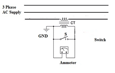
This type is used in power transmissions to step down the current of the circuit to a lower reading so that it can be easily read by a lowly-rated ammeter (5A ammeters).
A current transformer has two windings: one for the primary winding and one for the secondary winding. The primary winding is connected to the source of power while the secondary winding is connected to a load and in this case, is usually the ammeter.
For example, if you have an electrical circuit with 12V at 100A and you want to read its current value, you will connect your ammeter between the source and secondary winding of your current transformer. The current running through this circuit is 100A so it will give 12A on your ammeter.
The secondary terminal has more turns than the primary one.
Keep in mind that the ammeter has some resistance. This directly implies that the secondary section of the CT is designed to operate even in short-circuited circumstances.
One of the terminals that make up the secondary section is grounded or earthed. The purpose of the earthing is to shield the ammeter from the dangers of high voltage.
The earthing also protects the operator from accidents related to high voltage.
Voltage transformers (VT)
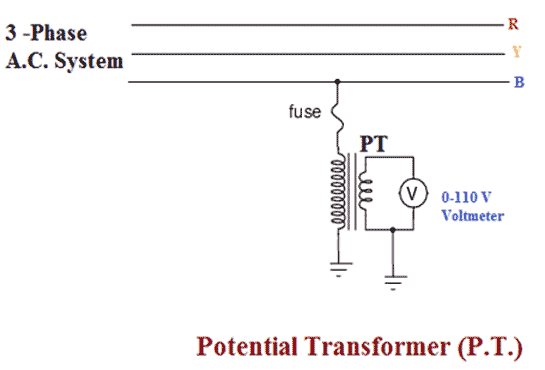
Also known as Potential Transformer (PT), this type is used in power transmissions to step down the voltage of a circuit so that it can be easily read by an ammeter or voltmeter. This type of instrument transformer makes it possible to use a small voltage (110V) to measure the voltage of the circuit.
The primary section of the VT has more turns than the secondary terminal. It is designed to handle the large current. The secondary section is made of smaller turns. It is designed to deliver only a small amount of current.
The secondary winding of the VT has one end that is connected to the earth and the other end has a number of turns that are connected to the rest of the circuit.
Also, these secondary terminals have fewer turns than the primary winding. This design makes it perfect to be used mostly in open-circuited conditions.
This type of transformer has two terminals, one for the earth and another for the current supply. The earth terminal is connected to the body frame and the other terminal for the current supply is connected to the primary winding.
One section of the secondary winding is earthed to balance the voltage with the earth. This shields the voltmeter, ammeter, and the operator from the dangers of high-voltage circumstances.
What is the difference between CT and VT?
We have just looked at the basic definitions of the current transformer and voltage-current instrument transformers. Let’s outline the differences between these two:
The first difference is in the connection with the circuit. CT is usually connected in series with the power circuit. On the other hand, VT is connected in parallel with the power circuit.
Instrument connected: Since CT is mainly concerned with the current passing through a circuit, it is connected to the ammeter. VT on the other hand is connected to the voltmeter.
Nature of the circuit: CT works perfectly in short circuited conditions. VT on the other hand is designed to work in the open-circuited condition.
In both CT and VT, one terminal of the secondary must be earthed for protection against the dangers of high voltage.
Advantages of instrument transformers
Are instrument transformers that valuable? Regardless of the type, there are several advantages or benefits that you are likely to get from using instrument transformers.
Here are the top benefits of instrument transformers.
-Can measure high AC current and voltage: Let’s say you want to determine the current flowing through a circuit yet the incoming current or voltage is so high. An instrument transformer will come in handy in such situations. You can easily use it to get the final values regardless of the quantity of the source current or voltage.
-Provides electrical isolation: The working mechanism of instrument transformers entails providing electrical isolation between the power source and the measuring instrument. This isolation is necessary to prevent the harm of electrical shock or electric shock.
-Easy to use: Instrument transformers are easy to use and are also inexpensive. You can easily install them on your circuit. The installation process is also very simple and doesn’t require special skills. Once installed, you can easily operate it by just plugging or unplugging the power source from it.
-Highly efficient: Instrument transformers are highly efficient because they have high efficiency than their counterparts such as primary and secondary transformers. In a nutshell, instrument transformers consume less power than their counterparts do and hence save on energy costs.
-Safety of user and instrument: Instrument transformers are safe for both the users and the instruments. They are safe for the user because, in case of the circuit’s failure, it will automatically switch off thus preventing the harm of electric shock. On top of that, instrument transformers are also safe for instruments because they isolate them from any electrical contact or current. This is why instrument transformers are very efficient and effective.
-High quality: Instrument transformers have high quality as they are made with high-quality materials and parts. These parts have superior qualities such as efficiency, durability, and reliability.
-High reliability: Instrument transformers have high reliability because they are built to withstand harsh environments such as extreme temperatures, moisture, and pressure which make them more durable than their counterparts.
What are the disadvantages of instrument transformers?
The main drawback of the instrument transformers is they can only be used with AC circuits. You cannot use these transformers on your DC circuit.
Testing instrument transformers
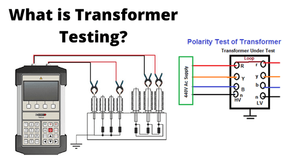
After buying an instrument transformer, it is important to test it before you fully integrate it into the circuit. Testing will ensure that the transformer is not only in good working condition but also capable of delivering accurate results.
There are a number of activities that you should undertake when testing an instrument transformer. One of them is to adjust the transformer settings to match the requirements of the circuit and the measuring instruments involved.
You can also adjust the insulation, windings polarity among other parameters that determine the working and operations of the instrument transformer.
Conclusion
Now you have all the details about the instrument transformer, the next step is to make the right purchase. You should first decide on the type of instrument transformer that will fit your application. From there you can choose the best manufacturer or supplier.
At ICRFQ, we are a trusted sourcing agent for instrument transformers in China. We can help you get the best transformer at an affordable cost.
If you want to find more Electronic Components Distributors, please check out the following articles:
Electronic Components Distributors In the USA
Electronic Components Distributors In UK
Electronic Components Distributors In China
Electronic Components Distributors In India
Electronic Components Distributors In Singapore
Electronic Components Distributors In Malaysia
Electronic Components Distributors In Vietnam
Electronic Components Distributors In South Korea
- Where to buy IC chips? The Best Guide? - March 26, 2024
- Breaking Down Barriers: Overcoming Obstacles in Cross-Border Electronic Component Trade - March 4, 2024
- Everything You Need to Know About Amplifier IC Chips - March 4, 2024


