
Last Updated on October 24, 2023 by Kevin Chen
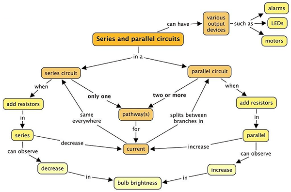
Image Source: Flickr
When you think of electricity and circuits, what comes to mind? If you’re like most people, you’ll probably think of series and parallel circuits. After all, these are the two most common types of electric circuits used in everyday devices and appliances.
But how do they differ? Which one is better for a given project? Here we explain everything you need to know about series vs parallel circuits before starting your next project.
What is a Series Circuit?

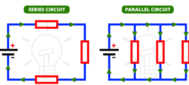
In a series circuit, all electrical components are connected end to end. This means that the current travels through every component until it reaches the end, where it is discharged.
This is shown in the diagram below. A series circuit has only one path for current to flow, which means that voltage and current are the same across the entire circuit.
The main advantage of series circuits is that it makes the circuit easier to analyze when troubleshooting. Since the current is the same throughout the whole circuit, you can calculate the resistance of one part of the circuit and the voltage drop of the whole circuit by knowing only two values, which makes calculating and troubleshooting the circuit much easier.
What is a Parallel Circuit?
In a parallel circuit, the components are connected side by side. This means that each component has its own independent path for current to flow.
The diagram below shows an example of a parallel circuit. A parallel circuit has multiple paths for current to flow, which means that the voltage across each path is the same and the current is the same throughout the whole circuit.
The main advantage of parallel circuits is that the voltage drop is distributed between the components, meaning that each component experiences less voltage drop than it would in a series circuit.
The disadvantage of this is that all components must have the same current capacity. If one component in a parallel circuit has a higher current capacity than the others, it will end up taking all the current and becoming damaged.

Parallel vs Series Circuits: What’s The Difference?
Let’s now analyze the key areas of difference between series vs parallel circuits.
Definition
As we have defined, a series circuit is one in which the current must pass through every component in the circuit.
For example, a series circuit is a circuit where light bulbs are connected end to end so that all bulbs share a common return path.
On the other hand, a parallel circuit is one where components are connected side by side with each other and there exist multiple paths for current to flow. so that all branches share a common return path.
Voltage distribution
In a series circuit, each device receives the same voltage as every other device connected in the chain. This means that the voltage at each point of the series circuit is the same as the source voltage.
On the other hand, in a parallel circuit, each device receives a different voltage from every other device. Let’s say we have three bulbs connected in parallel with a battery. In this case, bulb one gets 1/3 of the battery voltage, bulb two gets 2/3 of the battery voltage and bulb three gets 1/3 of the battery voltage.
Current distribution
In a series circuit, all components receive equal current as they share the same path. This means that all components have equal current ratings.
On the other hand, in a parallel circuit, all devices are not required to have equal current ratings because there are multiple paths for current to flow through.
Voltage drop
In a series circuit, the total voltage is equal to the sum of the voltage drops across each resistor.
This means that if we have two resistors with values of 10 Ω and 20 Ω connected in series, the total voltage across both resistors will be 30 V.
The reason for this is because the current flowing through both resistors is equal and thus they share equal voltage drops.
On the other hand, in a parallel circuit, there are multiple paths for the current to flow through so it doesn’t matter how many paths there are or which path the current flows through.
This means that for any given resistor, there may be multiple paths for current to flow through but as long as all paths have an equivalent resistance then all paths will carry equivalent amounts of current; therefore, there will be no effect on the voltage drop across each resistor.
Fault occurrence
In a series circuit, a fault on one device or component will result in a total breakdown of the circuit. This is because there is only one path for current to flow through and as soon as the path is broken, the circuit will be completely disconnected.
In a parallel circuit, however, a fault on one device or component will not result in a total breakdown of the circuit. This is because there are multiple paths for current to flow through and as long as one path still exists then current can still flow through the circuit.
Total resistance
In a series circuit, the total resistance is simply the sum of all the individual resistors in the circuit. This can be illustrated by the equation;
R= R1+R2+R3
In a parallel circuit, however, the total resistance is the inverse of the sum of the reciprocals of all the resistances. This can be illustrated by the equation; R= 1/ (1/R1+1/R2+1/R3)
Arrangement
In a series circuit, all the components are arranged in a single line or a single path. In a parallel circuit, the components are parallel to each other. This means that in a parallel circuit, the components are arranged side by side.
Coordination
In series circuits, the voltage of each branch is added together to give the total voltage across the circuit. In parallel circuits, each branch is connected in parallel to all other branches.
This means that in a parallel circuit there will be multiple paths for current to flow through and as long as one path exists then current can flow through it.
Performance of individual components
In a series circuit, you are likely to record an underwhelming performance of the individual electric components.
For example, the bulb may not be as bright as compared to if you had connected it to a parallel circuit. However, in a parallel circuit, all the components will be working simultaneously, and therefore, the light bulb will be working at its full capacity.
Losses
In a series circuit, each component has a certain amount of power but the overall power is less than what it would have been if you had connected it in parallel. This means that you are likely to lose some of the power that is being produced by your electric appliances.
However, in a parallel circuit, all the components work together, and therefore, they are able to produce more power as compared to what they would have been capable of individually.
Pros of Series Circuits
– Series circuits are easier to analyze when troubleshooting since the current is the same throughout the whole circuit.
– Series circuits are generally easier to design than parallel circuits because you only have to consider the current and voltage of one component.
– Series circuits are generally easier to build than parallel circuits because you only have to connect one component at a time.
– Series circuits are often used to reduce voltage because the voltage drop is distributed across the components.
– Series circuits can be used to increase voltage if all components are chosen to have a higher current capacity than the available current.
Cons of Series Circuits
– They are not suitable for use with multiple loads because they do not have an independent path for each load.
– Series circuits usually have high voltage drops because the voltage drop is distributed across the components.
– These circuits are not suitable for use with inductive loads because the current will increase as the voltage drop increases.
– Series circuits are not suitable for use with capacitive loads because the voltage will increase as the current increases.
– Multiple components connected in series have a lower total voltage rating.
Pros of Parallel Circuits
– Parallel circuits are easier to design because you only have to consider the current of each component.
– They have lower voltage drops and current drops than series circuits because the voltage drop is distributed across the components.
– If one component gets damaged, the others will continue operating as usual. This is one of the advantages that come with the independence of these circuits.
– These circuits are often used to increase current since each component takes its full current.
– They are suitable for use with multiple loads because each load has its own independent path for current.
Cons of Parallel Circuits
– Parallel circuits are more difficult to analyze when troubleshooting since you have to consider the voltage and current for each component.
-Dofocult to introduce an additional voltage source. This is because the voltage is divided among the components.
-Requires lots of wires for the connections. As we have already stated parallel circuits involve lots of branches and in each branch, you will need wires, cables, and other connectors. This directly means that you will have to spend more on these resources.
When Should you Use Series Circuits?
Series circuits are commonly used to decrease voltage. This is commonly done to prevent the voltage drop in a circuit from exceeding the rating of the circuit breaker.
Series circuits are also commonly used in circuits that require very low voltages such as voltages below 100 volts.
Series circuits are also sometimes used to increase voltage if all components in a parallel circuit have a lower current capacity than the current being supplied to the circuit.
When Should you Use Parallel Circuits?
Parallel circuits are commonly used to increase voltage. This is commonly done to prevent the voltage drop in a circuit from exceeding the rating of the circuit breaker.
Parallel circuits are also commonly used in circuits that require very high voltages such as voltages above 100 volts. Parallel circuits are also sometimes used to decrease voltage if all components in a series circuit have a higher current capacity than the current being supplied to the circuit.
What are some example applications of series circuits?
The most common applications include;
-Holiday lamps (Christmas lights)
-Christmas tree lights
What are examples of applications in parallel circuits?
These applications include;
-Home lighting system
-Electrical outlets
-Lights in a room
-Electrical outlets
Can a circuit have both series and parallel circuits?
Yes, some circuits can have both series and parallel circuits.
For example, a circuit that has a series circuit on one side and a parallel circuit on the other side can be used to increase voltage or decrease voltage.
Such circuits are also called “series-parallel combinations”.
Circuits that have both series and parallel circuits are commonly called “mixed series-parallel circuits”. They are used when it is not possible to use one type of circuit for both functions.
For example, a circuit that has a series circuit on one side and a parallel circuit on the other side can be used to increase voltage or decrease voltage.
Buying electronic components for circuits
Whichever circuit you use, ensure that you use the right electric components. Using a faulty component can make your circuit fail. They can even increase the cost of running the circuit.
This is why we at ICRFQ, as a sourcing agent, are committed to delivering quality electronic components in China
Key takeaway
Series and parallel circuits are both used in electrical circuits. Despite their major differences, it is important to be cognizant of the fact that both are used for the same purpose-to supply and distributing power to different electric loads.
So, while you may be tempted to use the wrong circuit type in a given situation, it is best to always choose the circuit type that is most suitable for the load being served.
If you want to find more Electronic Components Distributors, please check out the following articles:
Electronic Components Distributors In the USA
Electronic Components Distributors In UK
Electronic Components Distributors In China
Electronic Components Distributors In India
Electronic Components Distributors In Singapore
Electronic Components Distributors In Malaysia
Electronic Components Distributors In Vietnam
Electronic Components Distributors In South Korea
- Where to buy IC chips? The Best Guide? - March 26, 2024
- Breaking Down Barriers: Overcoming Obstacles in Cross-Border Electronic Component Trade - March 4, 2024
- Everything You Need to Know About Amplifier IC Chips - March 4, 2024


