
Last Updated on April 10, 2022 by Kevin Chen
The inductor, a coil-like structure found in most circuits, is one of the most magical amulet electronics components. These characteristics are due to the operation of transformers and other power electronic circuits.
Inductors are commonly utilized as energy storage devices in DC-producing switched-mode power devices. The inductor supplies the circuit, which stores energy, to maintain current flow during “off” switching periods, allowing topographies where output voltage exceeds input voltage.
Many people find it challenging to comprehend how they function, affecting the electric and magnetic fields.
A magnetic flux is created around a wire conductor when an electrical current travel through it. The direction of the magnetic flux circulating the conductor and the current flowing through the same conductor is related to this effect. The “Fleming’s Right-Hand Rule” results from this link between current and magnetic flux direction.
However, another critical aspect of a coiled-coil is that the movement of the magnetic flux opposes or resists any changes in the electrical current passing through it, causing a secondary voltage to be inducted into the same coil.
An inductor is nothing more than a coil of wire twisted around a central core in its most basic form. The current passed through most coils generates a magnetic flux (N) around it that is proportional to the electrical current flow.
What is an inductor?
An inductor is the most basic of all electrical components. A passive two-terminal electrical component stores energy in a magnetic field when electric current flows. An inductor is often made up of an insulated wire twisted into a coil, similar to a resistor. After significant trial and error, this design was chosen using Hanna curves and the area-product approach.
The time-varying magnetic field produces a voltage in the wire that is polarized in the opposite direction as the current change created when the current in the coil varies. As a result, inductors resist all current fluctuations that flow through them.
The induced magnetic field also causes an electrical property called inductance, defined as the ratio of voltage to the current rate of change. The amount of energy that an inductor can store is measured by its inductance.
Inductor Design and Key Components
The electrical, mechanical, and thermal requirements of a specific application dictate the design of an inductor. It entails, in general:
- Choosing a core material
- Selecting a core size and shape
- Choosing the suitable winding wire
An enamel-coated magnetic wire, usually composed of copper, is used as the core material, subsequently covered in layers of insulating polymer material. The winding can create a variety of cross-sections, including circular, rectangular, and square foil. A magnetic wire is chosen to restrict and guide the magnetic fields, and it is insulated to prevent problems like short circuits and failures.
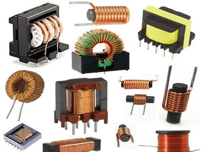
The Different Types of Inductor
Different types of inductors are required for various applications. To facilitate the development of a strong magnetic field, an inductor in a system is usually always constructed around a core material—generally iron or iron compounds.
Iron Core Inductors
Iron is the most well-known and widely used magnetic material, making it ideal for inductors. Iron inductors, as previously said, have an iron core. Because of their enormous inductances, they are commonly employed for low-frequency line filtering.
They’re also commonly used in audio equipment. However, inductors do not always require an iron core.
Air Core Inductors
As the name implies, the core of air-core inductors is open air. Air core inductors have low inductance because air has a low permeability. This means that the current rises quickly in response to an applied voltage, allowing them to handle high frequencies found in applications like RF circuits.
Ferrite Core Inductors
A ferrite is a ceramic substance formed by combining iron (III) oxide with small amounts of one or more additional metallic elements, such as nickel and zinc, then burning it. Inductors are made by combining ferrite powder with epoxy resin and molding it into a core around which a magnetic wire can be wound. Ferrite inductors are the most popular because their permeability can be accurately controlled by adjusting the ferrite to epoxy ratio.
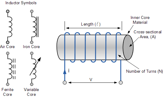
Inductor Symbol
The magnetic flux is proportional to the current I flowing through it. Because of the build-up of self-induced energy within its magnetic field, an inductor, unlike a capacitor, opposes the rate of change of current flowing through it.
Inductors, in other words, resist or oppose current fluctuations while fast passing through a steady-state DC. Inductance is the ability of an inductor to withstand variations in current and to relate current, I, to its magnetic flux linkage, N, as a constant of proportionality. The symbol L denotes it with Henry (H) units after Joseph Henry.
Because the Henry is a relatively big unit of inductance in its own right, subunits of the Henry are employed to signify its value for smaller inductors. Consider the following scenario:
Inductance Prefixes
| Prefix | Symbol | Multiplier | Power of Ten |
| milli | m | 1/1,000 | 10-3 |
| micro | µ | 1/1,000,000 | 10-6 |
| nano | n | 1/1,000,000,000 | 10-9 |
So, to show Henry’s sub-units, we’ll use the following example:
- 1mH = 1 milli-Henry – equal one-thousandth (1/1000) of a Henry.
- 100μH = 100 micro-Henries, equal to 100 millionth’s (1/1,000,000) of a Henry.
In electrical circuits, inductors or coils are pretty frequent. The shape of the coil, the number of turns of the insulated wire, the number of layers of wire, the spacing between the turns, the permeability of the core material, the size or cross-sectional area of the core, and so on are only a few of the elements that influence the inductance of a coil.
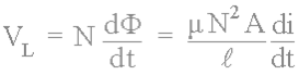
Inductor coils have a center core area (A), and a fixed number of wire turns per unit length ( l ). As a result, if a coil of N turns is connected by an amount of magnetic flux, the coil has a flux linkage of N, and every current I running through the coil produces an induced magnetic flux in the opposite direction of the current flow. Then, according to Faraday’s Law, any change in this magnetic flux connection results in a self-induced voltage of:
Where N denotes the number of turns, A is the cross-sectional area in square meters. Φ In Webers is the quantity of flux. μ is the core material’s permeability, l is the coil’s length in meters, and di/dt is the current rate of change in amps/second
A time-varying magnetic field produces a voltage proportional to the current rate of change. A positive value indicates an increase in emf, and a negative value indicates a reduction in emf. Substituting N2A / l for L, the constant of proportionality known as the coil’s inductance yields the equation linking self-induced voltage, current, and inductance.
N = Li is the relationship between the flux in the inductor and the current flowing through it. Because an inductor is made up of a coil of conducting wire, the previous equation is reduced to yield the self-generated emf, also known as the back emf induced in the coil:
Practical Applications
Inductors are typically pricey due to the copper and iron components required to manufacture them. As a result, most of their uses are limited to areas where such an investment may be justified, such as telecommunications equipment, radios, and power supply.
The purpose of an inductor in a power supply is to prevent rapid changes in current. An inductor prevents abrupt fluctuations in the power supply’s output voltage and current in conjunction with a capacitor. They’re relatively simple components that play an essential function in power electronics.
Power Inductor Summary
An inductor, also known as a choke, is a passive electrical component of a coil of wire designed to take advantage of this relationship by producing a magnetic field in itself or inside its core due to current running through it. The magnetic field produced by forming a wire coil into an inductor is substantially stronger than that produced by a simple wire coil.
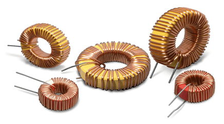
Inductors are created by tightly wrapping wire around a solid central core, either a straight cylindrical rod or a continuous loop or ring, to concentrate their magnetic flux.
A coil of wire is the schematic representation for an inductor. As a result, a coil of wire can also be referred to as an inductor. Inductors are classified by the inner core they have wound around, such as hollow-core (free air), solid iron core, or soft ferrite core inductors. The addition of continuous or dotted parallel lines close to the wire coil distinguishes the various core types.
Conclusion
As electronic devices get more complex, LSIs’ power supply voltage is dropped, allowing them to consume less power while increasing their speed. However, as the power supply voltage is reduced, the requirements for voltage fluctuations grow more stringent, necessitating the adoption of high-performance DC-DC converters to meet these needs. Power inductors are critical components that significantly impact how well they work.
TDK offers a wide range of power inductor devices. According to the required properties of DC-DC converters, this page describes and explains practical techniques for employing power inductors and essential factors for selecting them.
Inductors are a vital component in our electrical devices and machines. If you are planning on purchasing them, contact us at ICRFQ. We manufacture the best electrical components, especially power inductors, in China.
If you want to find more Electronic Components Distributors, please check out the following articles:
Electronic Components Distributors In the USA
Electronic Components Distributors In UK
Electronic Components Distributors In China
Electronic Components Distributors In India
Electronic Components Distributors In Singapore
Electronic Components Distributors In Malaysia
Electronic Components Distributors In Vietnam
Electronic Components Distributors In South Korea
- Where to buy IC chips? The Best Guide? - March 26, 2024
- Breaking Down Barriers: Overcoming Obstacles in Cross-Border Electronic Component Trade - March 4, 2024
- Everything You Need to Know About Amplifier IC Chips - March 4, 2024


