
Last Updated on October 22, 2023 by Kevin Chen
In a variety of industries, a pulse transformer is one of the most extensively used bespoke transformers. Vacuum devices, in general, operate on high-power pulse voltage created by high-power pulse transformers. The structure of these transformers is compact, and the repeatability is excellent. Wide pulse width, low rising time, and high energy efficiency are all expected in most applications.
These transformers are primarily used to distribute power and hold large loads. Compared to a standard transmitter of similar size, these can transmit massive amounts of power and operate at high frequencies. There are numerous reasons why these transformers are frequently regarded in various industrial fields. The purpose of this article is to provide an explanation of a pulse transformer and how it works.
What Is A Pulse Transformer?
A pulse transformer is a transformer that has been upgraded to create electrical pulses with stable amplitude and high velocity. These are commonly used in digital data transmission and transistors, primarily in gate drive circuits. Distributed capacitance and galvanic isolation are required features of the ideal transformer. Capacitance with minimal coupling is also essential for circuit safety.
Pulse transformers can handle many signals, from complementing logic drives to transmission lines. These transformers operate at lower power levels. A few of these transformers can be used as wideband transformers.
Transformers for digital data transmission has been modified to reduce signal distortions. Exterior properties such as each individual winding capacitance, inter-winding capacitance, and resistance can be used to assess frequency range and signal conformance.
Overshoot, Droop, backswing and fall time, and a delayed rise are all negative repercussions of these traits. Frequency range, inductance, operating frequency, voltage ratings, size, power grades, resistance, and winding capacitance all influence the design of pulse transformers.
Signal and power are the two forms of signals that are commonly used. Each has its own pace, but they all have a high open-circuit inductance and a limited tolerance for dispersed capacitance and leaky inductance. Any pulse-based transformer can be challenging to put together; however, assembly kits for do-it-yourselfers or electrical hobbyists are widely available.
How Does a Pulse Transformer Work?
“Pulse converters” and “pulse transformers” are two different terms for the same thing. They change the direction of electric power from AC to DC. In the industry, pulse transformers are commonly used to convert AC power to DC power and vice versa.
Electromagnetic induction is used to operate pulse transformers. An electromagnetic field is created when a current is carried through a coil of wire. This field causes a voltage to be generated in a nearby coil of wire.
Pulse Transformer Voltage
Handle supply and current as a pulse transformer to appropriately source and load electronic and electrical equipment. Pulse transformers are utilized in various applications, including radar, television, and digital computers—the output voltages of a conventional pulse transformer range from 100kV to 500kV.
Pulse Transformer Design
The impedance, winding capacitance, inductance, size, power rating, low to high voltage level, operating frequency, frequency response, packaging, and other characteristics all play a role in the design of a pulse transformer.
Through winding topologies that maximize the coupling among the transformer windings, designers strive to reduce parasitic factors such as winding capacitance and leakage inductance. By incorporating multiple standard type constructions, this transformer can be constructed in a variety of sizes and shapes by manufacturers such as Butler Winding. Pulse transformers are tiny and have fewer turns than conventional transformers. As a result, the leakage inductance of the transformer’s windings is low, and the interwinding capacitance is low.
The pulse transformer has a high magnetizing inductance because the cores are made of ferrites rather than wrapped strips of high permeability alloys. Insulation with high voltage is used between 2 windings and toward the ground in these transformers. These transformers usually handle the pulse signal but can also train it.
The performance of an impulse transformer is primarily determined by its effect on the shape of the pulse input voltage or current. Small pulse transformers are commonly found in computers, pulse generators, and other electronic devices. Large pulse transformers, which can produce 50 to 100 MW of power at 200 to 300 kV in a few microseconds, are primarily employed in radar systems.
The Primary Purpose of a Pulse Transformer
Transformers, in general, conduct electricity and filter signals in a regulated, calculated manner to various outposts. Pulse-based transformers are similar to other types of transformers but differ in how they regulate output. Rectangular electrical pulses have a fast fall and rise period, making them ideal for applications that require energy dumping or switching elements. The tiniest variants are utilized in handheld electronics and a wide range of digital applications. Larger transformers are frequently required for flow control in high-power semiconductors, among other applications.
Signal Types of a pulse transformer
The device’s size and, as a result, the overall transformer design dictates its function. The two most prevalent types of pulse transformers are signal and power pulse transformers. Smaller transformers called signal types are employed to generate a sequence of pulses at low power levels. They’re used in circuits such as digital logic and telecommunications when only a few volts are required for a few microseconds. Lighting is one of the many applications for small pulse-generating transformers.
Types of Pulse Transformer
The two most prevalent types are signal and power pulse transformers. Power transformers modify the voltage level or phase configuration at the power level. They are available in single-phase and three-phase primary configurations, with different means of winding coupling. Signal transformers are electromagnetic induction-based pulse transformers that transmit data from one circuit to another. They’re commonly utilized to boost or lower the voltage between two power transformer sides. The number of windings divided by the turn ratio determines the voltage difference in signal transformers.
Pulse transformers are high-frequency transformers with low-loss cores. The winding configuration is meant to optimize coupling to reduce parasitic factors like winding capacitance and leakage inductance. Pulse width, Range, input voltage, repetition rate, current, duty cycle, output voltage, frequency, and physical dimensions like width, length, and height are among the performance criteria for pulse transformers. The average number of pulses per unit of time (usually seconds) over a given period is known as pulse repetition rate or frequency. The interval between the first and last times the instantaneous amplitude reaches a certain fraction of the peak pulse amplitude is known as pulse width or pulse length.
Construction of Pulse Transformer
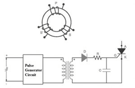
The pulse transformer’s primary role is to provide electrical isolation while producing a signal for a semiconductor device. The image below depicts a toroidal-shaped pulse transformer with two main and secondary windings. Below is a diagram of how a pulse transformer is made.
- Every winding contains equal turns, allowing any winding to function as a primary or secondary winding.
- The signal to the silicon-controlled rectifier can be sent in a 1:1 ratio or a 1:1:1 ratio to the transformer.
- The 3-winding-based transformer can supply a constant signal to the SCR.
- The second diagram can show the gate signal of the firing circuit via the pulse transformer.
- The role of the series resistor is to limit the holding current of the rectifier.
- To avoid reversing gate current, the diode ‘D’ is employed, and a 1:1:1 pulse transformer can be used to generate a continuous pulse for the SCR.
Above is a three-winding pulse transformer. This transformer’s design can be done with excellent efficiency. The primary winding’s inductance must be large to reduce the magnetizing current. The direct current supplied across the transformer’s primary winding can prevent the core from being saturated.
The insulation between the two windings of the transformer can safeguard the transformer’s winding. As a result, strong coupling between two windings is required. The stray type of signal provides a lane within the high frequency inter-stage capacitance.
On the output signal, there is a frequency influence. For high signal frequencies, the output signal’s shape and frequency are identical to the input signal’s.
As a result, the output is proportionate to the amount of input at low signal frequencies.
Specifications of Pulse Transformer
The pulse transformer’s specs include different parameters connected with o/p response. These parameters will define the acceptable pulse distortion limits.
Pulse Amplitude
Besides the meaningless spikes, the pulse amplitude is the signal’s maximum peak value.
Rise Time (Tr)
The time it takes for the output signal to increase from 10% to 90% of peak pulse amplitude in the initial attempt is called rise time. In some circumstances, it can be defined as the time it takes for the output signal to increase from zero to pulse amplitude for the first time.
Over Shoot
Overshoot is the output signal that surpasses the peak amplitude.
Pulse Width
Pulse width or pulse duration is the period between the first and last instants when the instantaneous amplitude reaches 50% of the peak amplitude.
Droop
Droop, commonly known as tilt, is the amplitude movement of a pulse across its level response.
Fall time (Tf)
The time it takes to drop the peak amplitude of the output signal from 90% to 10% across the trailing edge’s response is known as fall time. Decomposition time is another name for it.
Backswing
The backswing is the portion of the trailing edge that grows below the level of zero amplitude.
Advantages & Disadvantages of Pulse Transformer
The following are some of the benefits of using a pulse transformer.
- It is of a small size.
- It is inexpensive and has a high isolation voltage.
- It works at a very high frequency.
- It can transmit high-energy signals.
- There are more windings in it.
- It keeps stray currents at bay.
- Insulation and control are provided.
The following are some of the downsides of using a pulse transformer.
- Both output waveforms are distinct at low frequencies. DC supplies are distributed throughout the primary winding to keep the core from becoming saturated.
- Saturation occurs at lower frequencies with this type of transformer. As a result, it can only be used at the highest frequencies.
- Because of the magnetic coupling, the signal is hazy.
Summary
A rectangular electrical pulse is transported by a pulse transformer, which is an electrical transformer. Signal types are widely used to match logic drivers to transmission lines in digital logic and telecommunications circuits. Medium-sized power versions are required for power-control circuits like camera flash controllers.
Larger power versions are used in the electrical power distribution sector to connect low-voltage control circuitry to power semiconductors’ high-voltage gates. High-voltage pulse transformers are required for high-power pulses in particle accelerators, radar, and other high-energy pulsed power applications.
A pulse transformer must have distributed capacitance, low leakage inductance, and a high open-circuit inductance to reduce pulse shape distortion. Low coupling capacitance is necessary for power-type pulse transformers to protect the circuitry on the primary side from high-powered transients caused by the load.
High breakdown voltage and High insulation resistance are also necessary for this reason. Because a pulse with sluggish edges would induce switching losses in the power semiconductors, good transient response is required to retain the rectangular pulse shape at the secondary.
Pulse transformers are frequently described using the combination of the peak pulse voltage and the pulse duration (or, more precisely, the voltage-time integral)—the larger and more expensive the product, the costlier the transformer.
Due to the fact that pulse transformers have a duty cycle of less than 0.5, any energy accumulated in the coil during the pulse must be “dumped” out before the pulse can be fired again.
Conclusion
This article aims to provide an overview of the pulse transformer and how it works. The primary purpose of this transformer is to transfer electrical pulses, such as voltage or current pulses. This transformer links the signal from the main to the secondary winding to preserve the outline. The pulse transformer’s influence on the external signal’s contour can thus be used to evaluate its performance. As a result, the output signal’s contour determines its performance factor. After reading this article, we hope you are better equipped with a knowledge of what a pulse transformer is.
For more details or purchase of bulk but quality pulse transformer, contact us at ICRFQ. We manufacture the best electrical components in China.
If you want to find more Electronic Components Distributors, please check out the following articles:
Electronic Components Distributors In the USA
Electronic Components Distributors In UK
Electronic Components Distributors In China
Electronic Components Distributors In India
Electronic Components Distributors In Singapore
Electronic Components Distributors In Malaysia
Electronic Components Distributors In Vietnam
Electronic Components Distributors In South Korea
- Where to buy IC chips? The Best Guide? - March 26, 2024
- Breaking Down Barriers: Overcoming Obstacles in Cross-Border Electronic Component Trade - March 4, 2024
- Everything You Need to Know About Amplifier IC Chips - March 4, 2024


