
Last Updated on October 22, 2023 by Kevin Chen
There are different ways of naming circuits. One way is by naming them according to the electronic components that they have. It is under this that we have a resistor-inductor circuit, which is also always abbreviated as an RL circuit. Sometimes it is always referred to as RL filter or just RL network. Read on as w break down everything you should know about this type of electric circuit.
What is an RL circuit?
A resistor-inductor circuit is an electrical circuit that is used to filter a signal. It is a passive, linear, low-noise circuit that provides high-quality, low distortion, and low noise. These are the main characteristics of this type of electrical circuit.
The basic components of an RL circuit are a resistor and an inductor. The resistance of this type of circuit is always lower than the resistance of the actual signal to be filtered out. The inductance or inductance value in this case can be adjusted to control the amount of filtering done by the circuit in question.
What are the different types of RL circuits?
We can divide LR circuits into two major categories. These are the LR series circuit and the LR parallel circuits. Let’s have a brief look at each of these circuit types.
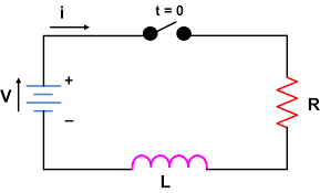
LR series circuit
In this circuit, the resistor and the inductor are connected in series. This means that the resistance of this circuit is always lower than the resistance of the signal to be filtered. It is a passive, linear, low-noise circuit that provides high-quality, low distortion and low noise.
The main advantage of this type of circuit is that it can easily be implemented in many different circuits. It is an ideal solution for filtering fast signals such as digital signals or digital data signals.
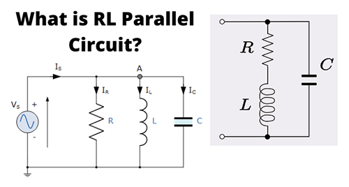
LR parallel circuit
In this type of circuit, there are two resistors and one inductor connected in parallel with each other. The main advantage of this type of circuit is that it requires only one power supply to carry out its filtering action on a signal. This makes it easier to implement in many different circuits since we do not have to make any changes to these circuits if we want to add filters into them. The filter output can also be adjusted easily by changing the values of either one or both resistors in the RL circuit.
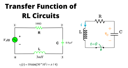
Expression of the LR circuits
There are various ways in which we can mathematically express the LR circuits. Also, the expression will depend on the type of LR circuit that we are dealing with. For instance, the expression for the series circuit will be different from that of the parallel circuit.
For the series circuit, we can express using the formula: I = R + L (1)
Where, I is the current flowing through the series circuit, R is the resistance of the series circuit, and L is the inductance of the series circuit.
For the parallel circuit, we can express using:
I = R + L (2)
Where I is the current flowing through the parallel circuit, R is the resistance of this circuit, and L is also known as “the mutual inductance”. The formula for the expression of the LR circuit can also be represented as:
I = R + L (3)
Where I is the current flowing through the circuit, R is the resistance of this circuit,and L is also known as “the mutual inductance”. To facilitate our understanding, we will now focus on a series-parallel hybrid circuits.
For this type of hybrid circuit, we first need to determine how much current passes through each branch. We can do this by using Ohm’s law and working out the ratio between each branch’s voltage and current. If we divide these two figures by each other, then we will have a ratio between voltage and current that passes through each branch. We can then plot these ratios on a graph which will represent how much current flows through each branch. This graph will look something like this:
We can then plot these ratios on a graph which will represent how much current flows through each branch.
Now that we know how much current flows through each branch, we need to determine what amount of power is needed to drive it so that it produces an output voltage at its terminals.
For instance, if one branch has an output voltage of 3 volts and another has an output voltage of 5 volts, then we know that in order for both branches to produce 3 volts at their output terminals.
What is the power factor of the RL circuit?
The power factor of the RL circuit is the ratio of the actual power delivered to the load to the apparent power delivered by the source. The power factor is a measure of how efficient a load is at converting energy from one form to another.
The formula for calculating the power factor of an RL circuit is:
P = λ / (1 − λ)
where:
P=Power factor
λ=Load impedance in ohms
Note that the power factor is a measure of how well an electrical load converts electrical energy into another form. In the case of an RL circuit, this is how well it converts electrical energy into ac (alternating current). The power factor is not a measure of how much power flows through the circuit. The power factor is a measure of how efficiently the circuit converts its input voltage to its output voltage.
This efficiency factor can be determined by plotting P versus V and then determining which curve has the highest slope at any given point on the graph. The slope of this curve will tell us how much power was actually delivered by the source (or voltage divider) and how much was converted to ac by the load (or resistor).
RL circuit differential equation
A differential equation is one that is written with two unknowns and one constant. In the case of RL circuit, the differential equation is:
idi=LRdt
Where:
LR=Load resistance in ohms
dt=Time in seconds
i=Current (in amperes.
What are the applications of RL circuits?
Just by looking at the arrangement and working of the RL circuits, you can tell that they have a wide range of applications.
Some application areas of these circuit types include:
-Communication systems: Systems such as the telecommunication systems are used for transmitting signals to and from a receiver.
-Electrical power: Power is often generated as an alternating current (AC) which is then converted to direct current (DC). For example, the power generated by a generator is converted to DC using an inverter.
-Electronic circuits: These circuits can be connected in series or in parallel depending on the application.
-Measurement systems: These are used for measuring the voltage of an electrical circuit and measuring the resistance of a circuit.
-Circuits in which we need to control the current: The control of current is very important in many applications. For example, in an electric stove, the power is controlled by a switch.
-Circuits for amplifying signals: In audio systems, we often use a transistor to amplify the signal and make it louder. A transistor amplifies a signal by using its transfer characteristic.
-Circuits with variable resistance: Variable resistance circuits can be used to make measuring instruments such as voltmeters and ammeters more accurate. Variations in the resistance of these circuits can also be used to measure temperature or humidity.
-Electronic oscillators: Electronic oscillators are used for generating radio waves and sound waves.
-Electronic filters: An electronic filter is a circuit that can be used to filter out unwanted noise or signals from an alternating current (AC) signal before it reaches a receiver. This type of circuit has many applications including radio communications and audio amplification.
While there are many other applications of RL circuits, I would like to list just one more application area in that RL circuits can be very useful in -the simulation of electrical networks.
In order for us to design electrical networks such as power grids, communication systems and lighting systems, we must simulate these networks using computer simulations.
Why are RL circuits important?
To understand the importance of RL circuits, it will be prudent to list down the key benefits of this particular type of circuit.
-Simple and easy to design: As we have seen, you don’t have to think about lots of electric components when it comes to designing LR circuit. This is because you don’t have to use inductors, capacitors and resistors which are the most important components of an RL circuit.
-Multi-functional: Since they can be used to generate both AC and DC signals, they can be used for many different applications such as audio systems, radio communication, and power generation.
-Versatility: There are many different types of materials that can be used for the construction of an RC circuit. This makes it very versatile since it can be used for many applications such as sound systems and radio communication.
-Low cost: As compared to other types of circuits that use various electronic components such as inductors, capacitors and resistors, the cost of building an RL circuit is low. This makes it very attractive for designers who are on a tight budget.
-Efficiency: Because the circuit has no active components like resistors, capacitors and inductors, it is highly efficient. This means that it can generate as much energy as it needs without wasting any of it.
-Linearity: The RC circuit is very linear in nature. This means that the output signal will be a perfect replica of the input signal.
-Low voltage drop: The voltage drop of an RL circuit is very low compared to other types of circuits such as LC and LC circuits. This makes it very suitable for applications where the output is required to be at a constant level or in a fixed range of voltage levels
-No noise: Since there are no active electrical components in an RL circuit, there will be no noise generated by this type of circuit. This makes it ideal for applications where noise generation is not a good idea because this could affect the performance of such an application.
What are the limitations of RL circuits?
The main problem that comes with incorporating RL circuits in an application is the fact that it is not possible to convert the output back into a form that can be used in other applications. This means that the output of this type of circuit cannot be used as input for another circuit.
One of the limitations of RL circuits is that they cannot be used with non-linear loads such as motors and light bulbs. This means that they cannot be used in applications where these types of loads are present because this could result in damage to the circuit.
What kind of filter is in the RL circuit?
A typical RL circuit is designed to work as a low-pass filter. This simply means that the output of the circuit is designed to have a frequency response that is much lower than the input signal.
This type of circuit is also ideally suited to applications where the input signal changes at a constant rate. This means that this type of circuit can be used in applications where there are no changes in the input signal and therefore, it will not be necessary for the output of this circuit to change over time.
What is the cutoff frequency of the RL circuit?
The cutoff frequency of an RL circuit is defined as the minimum frequency at which the output voltage of the circuit is equal to zero. This means that any input signal below this frequency will not be able to excite the circuit and therefore, it will have no effect on the output.
In order for an RL circuit to be able to operate at low frequencies, it must have a high Q factor. This means that there must be a large number of turns in the inductor and therefore, a large amount of magnetic flux needs to be present in this component. This can only happen if there are many turns in the inductor.
Conclusion
We have discussed all the essentials of the RL circuit and now you should be able to implement it to the fullest. And in case you would like to buy any component of this circuit, whether it is a resistor or inductor, remember to choose a reliable manufacturer. ICRFQ as a sourcing agent may help you pick one manufacturer for electronic components in China.
If you want to find more Electronic Components Distributors, please check out the following articles:
Electronic Components Distributors In the USA
Electronic Components Distributors In UK
Electronic Components Distributors In China
Electronic Components Distributors In India
Electronic Components Distributors In Singapore
Electronic Components Distributors In Malaysia
Electronic Components Distributors In Vietnam
Electronic Components Distributors In South Korea
- Where to buy IC chips? The Best Guide? - March 26, 2024
- Breaking Down Barriers: Overcoming Obstacles in Cross-Border Electronic Component Trade - March 4, 2024
- Everything You Need to Know About Amplifier IC Chips - March 4, 2024


