
Last Updated on October 24, 2023 by Kevin Chen
Thyristors are a fascinating semiconductor device class. They have features similar to diodes and transistors, which are silicon-based solid-state components. As a result, it may be difficult to identify thyristors from diodes and transistors. There are several distinct varieties of thyristors on the market to make matters more complicated. In some cases, the only thing that distinguishes thyristors is a minor detail. Depending on the manufacturer, a thyristor may also be known by a different name.
To properly use thyristors in circuit design, you must first grasp their characteristics, limitations, and relationship to the circuit. That’s why we’re making an effort to sort it all out so you can figure out which Thyristor is best for your application.
What is a thyristor?
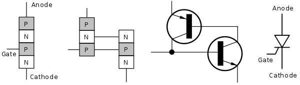
A thyristor is a four-layer device that alternates between P-type and N-type semiconductors on each layer (P-N-P-N). A thyristor has three terminals in its most basic form: anode (positive terminal), cathode (negative terminal), and gate (control terminal). The gate regulates the current flow between the anode and cathode.
A thyristor’s principal function is to operate as a switch to control electric power and current. It provides adequate protection to circuits with big voltages and currents for such a compact and light component (up to 6000 V, 4500 A). It’s attractive as a rectifier because it can switch from conducting to non-conducting current quickly.
Furthermore, it has a cheap maintenance cost and, when used properly, remains functioning for a long time without developing a flaw. From simple burglar alarms to power transmission lines, thyristors are employed in various electric circuits.
How does Thyristor work?
Let’s take a quick look at diodes to understand better how a thyristor works. A PN junction is formed by joining two semiconductor materials, one doped with P-type impurities and the other with N-type impurities, in a diode. Due to the first migration of electrons and holes across the junction, a depletion layer occurs, inhibiting the passage of charge carriers across the junction. The Barrier potential is the potential that has evolved across the junction as a result of the initial migration of charge carriers.
When the diode is linked to a voltage source greater than the barrier potential, the charge carriers overcome the block, and the diode begins to conduct. The forward bias is the phrase for this. The charge carriers travel further away from the junction when the polarity of the voltage source linked across the diode is reversed, and no conduction occurs. This is referred to as a backward bias.
The Thyristor comprises four layers of semiconductors that alternate between P and N. Consider a voltage source coupled to a P-N-P-N thyristor. In this situation, one of the Thyristor’s three junctions (the middle junction) would be reverse biased. The depletion region must be broken down for the gadget to conduct. The Gate-enabling method is used to accomplish this.
Electrons are injected into the P-region using a secondary voltage source connected between the gate and cathode terminal. The P-region eventually becomes swamped with electrons and transforms into an N-region. The bottom three layers have changed to N-type, while the highest layer has changed to P-type. As a result, it behaves like a PN junction diode, starting to conduct and continuing to do so even when the secondary voltage source is removed. This is the situation because enough electrons have been injected into the P-region and have traveled to the N-region.
When a sufficient positive signal pulse or current is applied to a thyristor’s gate terminal, it begins to conduct. A minimum current value is known as Holding current (Ih) is required to run the Thyristor in the ON state. The sum of current gains of both common base transistors must surpass unity at the semiconductor level for the Thyristor to switch ON (or latch on) and start conducting. The needed current is referred to as the Latching current.
How to switch off the Thyristor?
To turn a thyristor off, change the current flowing through it so that the sum of current gains is less than one. When the current value falls below the Holding current, the switch is turned off. They can also be turned off by using a tuned LC circuit in which they are exposed to variable voltage rather than a constant voltage.
The V-I characteristics of the cathode voltage Va and anode current Ia are obtained by providing the power source. The Thyristor is thought to have three modes of functioning based on the features discovered.
The three states of a Thyristor
So, how does it all work? We may place it in one of three states, either fully off or entirely on, implying that it’s a binary, digital gadget. It’s helpful to think about diodes and transistors when trying to comprehend how these states work:
Forward Blocking
A thyristor is normally shut off when no current flows into the gate: no current can travel from the anode to the cathode. Why? Consider the Thyristor as a combination of two diodes. Both the upper and lower diodes have a forward bias. However, because the connection in the center is reverse biased, the current cannot flow from the top to the bottom. This is referred to as forward blocking. Even though it is comparable to forward-bias in a normal diode, there is no current flow.
Reverse Blocking
The cathode is somewhat positive to the anode in this mode. There is no secondary voltage source attached. As a result, junctions 1 and 3 are forward biased, while junction 2 is reverse biased. The Thyristor consists of two diodes coupled in series with a reverse voltage source. The gadget only has a very modest leakage current on the order of microamperes. The Thyristor is now in the OFF position.
An avalanche develops at reverse-biased junctions when the applied reverse voltage surpasses a threshold known as the breakdown voltage, and the current grows fast. This could cause the device to overheat and break. As a result, the device’s reverse operating voltage should be lower than the breakdown voltage (Vbr). The Thyristor can be viewed as an open circuit in the reverse blocking mode since it has a high reverse impedance.
Forward Bonducting
The third state is the most fascinating. The anode must be positive, and the cathode must be negative. When current flows into the gate, it activates the lower transistor, activates the higher transistor, activates the lower transistor, and so on. Each transistor acts as a switch to turn on the others. This can be thought of as an internal positive feedback loop in which the two transistors keep feeding current to each other until they are both fully activated, at which time the current can flow from the anode to the cathode.
Forward conducting is how a thyristor “latches” (stays on permanently) in this state. When a thyristor is latched on like this, you can’t simply remove the current from the gate to turn it off: the gate current is meaningless at this point, and you have to interrupt the main current running from the anode to the cathode, which sometimes means turning off the power to the entire circuit.
How Is Thyristor different from MOSFET?
Both the Thyristor and the MOSFET are electrical switches that are widely utilized. The main distinction is that MOSFET switches are voltage-controlled devices that can only switch DC, whereas Thyristor switches are current-controlled devices that can switch both DC and AC.
How is Thyristor Different from Transistor?
Both a thyristor and a transistor are electrical switches; however, thyristors have a much higher power handling capacity than transistors. Because of the Thyristor’s high rating in kilowatts, transistor power is measured in watts. In this case, a Thyristor is analyzed as a closed couple pair of transistors. The major difference between a transistor and a thyristor is that a transistor requires constant switching power, but a thyristor requires a single trigger to stay on. Transistors can’t be used in applications like alarm circuits that need to trigger once and stay on forever. As a result, we use a Thyristor to solve these issues.
Classification of Thyristors
Thyristors are classed based on their ability to turn on and off and their V-I properties. Let’s take a closer look at each of them.
Thyristors with turn-on capability
Silicon Controlled Rectifier (SCR)
SCRs are the most widely used thyristors. Even after the gate pulse has been withdrawn, they can still conduct. Their properties make them suitable for phase control. Switching circuits, static switches, inverters, and DC motor drives all use them.
Reverse Conducting Thyristor (RCT)
Thyristors usually only conduct in the forward direction, inhibiting any reverse currents. On the other hand, an RCT combines an SCR with a reverse diode to eliminate superfluous loop inductances and voltage transients. RCT can run in reverse mode with reasonable commutation. These are used in high-power choppers’ inverter circuits and DC drives.
Light-Activated Silicon-Controlled Rectifier (LASCR)
Light-triggered thyristors are another name for them (LTT). When light particles reach the reverse-biased junction in these devices, the number of electron-hole pairs increases. HVDC transmission, high voltage pulse generators, and power compensators employ them.
Thyristors with turn-off capability
A suitable gate pulse can be used to turn on the thyristors discussed above. However, because the current does not automatically become zero, the supply current must be blocked to turn them off. The use of thermistors with turn-off capacity helps alleviates this annoyance.
Gate Turn-off Thyristor (GTO)
They’re also known as Gate-Controlled Switches (GCS) since the polarity of the gate current can be reversed to turn them off. It can be turned off ten times faster than a standard SCR. High-power inverters DC and AC motor drives all use GTOs.
MOS Turn-off Thyristor (MTO)
A GTO is coupled to a MOSFET in an MTO to enhance the switch-off time. A voltage pulse is applied to a MOSFET to switch it off. It stops latching by shorting the NPN transistor’s emitter and base. Motor drives, flexible AC line transmissions (FACTs), and high voltage applications up to 20 MVA all employ them.
Emitter Turn-off Thyristor (ETO)
It’s comparable to an MTO, except for the second gate terminal connected in series with the MOSFET. A negative voltage pulse is supplied to the MOSFET to turn off the ETO. Latching stops when the NMOS turns off and transfers all charges away from the cathode. High-voltage inverters, static synchronous compensators (STATCOM), and flexible AC line transmissions are used (FACTs).
Bidirectional Control
Two circuits must be coupled in anti-parallel to employ thyristors for AC voltage regulation, resulting in two control circuits. The complexity and number of wires increase as a result. As a result, bidirectional control thyristors have been designed, which may conduct in both directions when activated.
Triode for Alternating current (TRIAC)
TRIAC is a device with five layers. After SCRs, these are the most often utilized thyristors. They allow bidirectional current flow to regulate both halves of the alternating waveform. Due to their asymmetrical nature, they are often employed mainly for low-power applications. They’re utilized to manage the pace of numerous appliances and light dimmers.
Diode for alternating current (DIAC)
These are frequently used in tandem with TRIACs. They are wired in series with the TRIAC’s gate terminal. The DIACs prevent current flow through the TRIAC until a specific voltage level in the DIAC is attained, allowing symmetric triggering in either direction. They’re frequently found in light dimmers.
Silicon Diode for Alternating Current (SIDAC)
SIDACs are identical to DIACs, except that SIDACs have a higher voltage capacity and can be used as switches instead of triggers for other devices. Many special-purpose devices, such as Relaxation Oscillators, utilize them.
Applications of Thyristors
Here are a few examples of thyristor applications:
● They are typically utilized in direct high-voltage current (HVDC) transmission.
● They are employed at very high voltages and currents for switching and rectification.
● They’re employed in phase-fired controllers as control elements.
● In digital circuits, they are used as power supplies.
● They are employed as upgraded circuit breakers to prevent damage to the power system’s other components in the case of a breakdown.
● Crowbars are thyristors with a Zener diode connected to their gate terminal. A crowbar is preferable to a traditional circuit breaker or fuse.
● The theatre, television, and motion picture industries were the first to use thyristors on a big basis.
● In many applications, they have taken the place of rheostats and autotransformers.
Conclusion
Although thyristors are utilized in high voltage AC to DC rectification, other superior rectifiers, such as power MOSFETs, are employed for low and medium voltages. Because thyristors have a longer switching time due to bipolar conduction, MOSFETs can also be used in high-frequency applications.
On the other hand, Thyristors can resist up to 6000 V and 4500 A when it comes to high voltages and currents. They can quickly flip between conduction and non-conduction states. In addition to its benefits, it has a minimal maintenance cost and may work faultlessly for many years in the right atmosphere.
Lastly, for more details or purchase of any electrical components, contact us at ICRFQ. We are the best manufacturers in China.
If you want to find more Electronic Components Distributors, please check out the following articles:
Electronic Components Distributors In the USA
Electronic Components Distributors In UK
Electronic Components Distributors In China
Electronic Components Distributors In India
Electronic Components Distributors In Singapore
Electronic Components Distributors In Malaysia
Electronic Components Distributors In Vietnam
Electronic Components Distributors In South Korea
- Where to buy IC chips? The Best Guide? - March 26, 2024
- Breaking Down Barriers: Overcoming Obstacles in Cross-Border Electronic Component Trade - March 4, 2024
- Everything You Need to Know About Amplifier IC Chips - March 4, 2024


