
Last Updated on October 22, 2023 by Kevin Chen
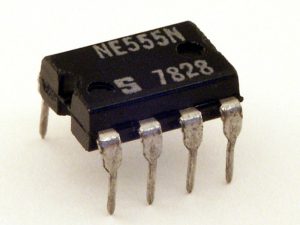
Image source circuit digest
Timer integrated circuits (or Timers, as they are commonly referred to) are integrated circuit devices used in digital circuitry that measure elapsed time in microseconds or milliseconds.
They are used in a range of electronics from simple timers for everyday use to complex industrial control systems.
It is a special type of IC that measures the time duration between two events and provides an output signal accordingly.
It can be used for measuring time intervals such as the elapse of a specific period of time, the number of times a specified event has occurred, or the remaining time on a timer.
This blog post will help you understand what a Timer is, its applications, and its features.
Read on to discover everything you ever wanted to know about this useful little device.
How Does a Timer Work?
The timer works by counting the number of times an input signal changes from low to high.
For example, if the input is a voltage that changes from 0V to 5V, the timer would be able to track how many times it completes this cycle.
The number of times the cycle is completed is the timer’s count.
The timer will finish counting at some point and output a signal based on what the timer was designed to do. In a timer, a capacitor is charged through a resistor until the input signal changes from low to high.
This discharges a capacitor through a resistor and charges the capacitor back up again.
This cycle continues until the capacitor reaches the voltage required to trip an interrupt. The interrupt is what trips the timer and lets it know it’s finished counting!
Construction of timer IC
A normal timer integrated circuit comprises three major electronic components. These are transistors, diodes, and resistors.
Transistors: These are used to control the flow of current in the circuit.
Diodes: These are used to rectify the current flow in a specific direction.
The diodes used here are known as “Schottky” diodes, which are used for low-power applications.
Resistors: These are used to control the voltage and current flow in a circuit and also for measuring time periods.
Resistor types include potentiometers, fixed resistors, variable resistors and thermistor resistors.
The three components are positioned in a way that the current from the battery is controlled by the transistor. The diode rectifies this current so that it flows in only one direction and the resistor is used to control the time period for which this current flows.
Other essential parts include a voltage divider, flip-flop, and a comparator.
A voltage divider is made up of resistors that create a self-reference voltage.
The comparators, on the other hand, are used to compare the voltage levels of the voltage divider with a reference voltage. The comparator output is connected to the logical input of a flip-flop, which then generates an output signal using the logic OR function.
The two comparators are connected to three pins namely, Trigger, Threshold, and Control pins.
These three pins end up determining the outputs of the comparators which are fed to the R and S pins flip flop.
If the R is 1 the output of the flip flop will be 0 and if the S is 0, the output of the flip flop will be 1.
There is an external Reset pin R and it has the capacity to override the output of the flip flop.
Also, the output from the flipflop is connected to a transistor that discharges to the ground.
Pins on a Timer IC
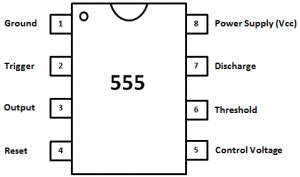
It is vital to know the different pins and what they do on timer integrated circuits.
GND Pin
This is the ground pin and is connected to the negative terminal of the power supply to the IC.
You should not connect this pin to any resistor because it is super sensitive. It may heat up due to the leaking current.
Trigger pin
The trigger pin sets off the timing cycle so that the Ic can start the timing operation.
The pin will be activated once it gets 1/3 of the supply voltage.
It is usually connected to the inverting inputs of the comparator and is designed to accept negative signals.
Clock pin
This is the clock pin and it has nothing to do with the timing operation.
It is connected to the positive terminal of the power supply.
The clock pin is also used as a reset in some ICs.
When triggered, it will reset the timer if it is not in use. If you want to start timing, you must connect this pin to the ground.
The clock pin should always be used. It can be used for other purposes like setting up an oscillator circuit or for controlling other circuits through the IC’s output pins.
It can be used as a reset for other circuits if required. The clock should always be kept low so that it does not get triggered by inductive loads like capacitors etc.
Reset pin
As the name suggests, its core role is to reset the IC. It is also connected to the positive terminal from where it can execute the reset perfectly.
It won’t work if connected to the ground.
VCC pin
This is the positive terminal from where the IC can take power. It should always be connected to the positive terminal of the power supply.
It can be used for other purposes like connecting an external device or for controlling other circuits through the IC’s output pins.
Discharge pin
This pin is used to discharge the capacitive load of the IC.
It can be used for other purposes like connecting an external device or for controlling other circuits through the IC’s output pins.
Enable pin
This is connected to the positive terminal from where it can receive power. It should always be connected to the positive terminal of the power supply. It can be used for other purposes like connecting an external device or for controlling other circuits through the IC’s output pins.
Threshold pin
The main function of this pin is to detect when the voltage on the timing capacitor goes beyond a certain threshold. It will react by turning on the transistor.
It can be used for other purposes like connecting an external device or for controlling other circuits through the IC’s output pins.
Operating modes of a timer IC
A timer integrated circuit has three main operating modes. These are Astable mode, mono-stable mode, and Bi-stable mode.
Let’s look at what these modes are and their key differences.
Astable mode
In this mode, the time IC produces conduction at the output terminals. This means that the IC is in a state of continuous conduction.
The duration of this mode is determined by the threshold voltage. The threshold voltage determines what level of current must be flowing through the transistor to make it conduct.
This mode is used when you want to generate pulses with a fixed frequency and duration, e.g., clock signals, timer signals, etc.
Mono-stable mode
In this mode, the time IC produces conduction only at one output terminal and remains off at other outputs. So it goes on and off periodically at intervals determined by an external signal or clock signal. This means that the IC is in a state of intermittent conduction. The duration of this mode is determined by the time interval between on-off cycles or pulses, e.g., timer signals etc.
The key difference between Astable and Mono-stable modes is that in Astable mode, all outputs are active simultaneously, whereas in Mono-stable mode, the output is active only for a certain time interval.
There are many types of ICs that use Astable mode as their primary mode of operation. Some examples include 555 timer circuits, 555 astable multivibrators, 555 monostable multivibrators, etc.
Bistable mode
This type of IC operation mode is also known as Schmitt trigger mode. It is normally used when the load has to be turned on and off continuously with the help of a push button.
In this mode, the IC is turned on and off by a mechanical switch or a microswitch.
Technical specifications of timer IC
Before you buy a timer integrated circuit, for whichever application, here are some of the key technical specifications that you should strive to know:
-Voltage range: Most timer ICs have a voltage range of between 5 volts and 18 volts. Your choice will also depend on the power requirements of the device in which you want to install the IC.
-Operational temperature: The range of operating temperature that you can expect from a timer IC is between -40°C and +85°C.
-Number of outputs: You should also be aware of the number of outputs that your particular timer IC has.
-Current consumption: The current consumption is usually given in milliamps. If you intend to operate this IC at very low currents, then you should consider buying an integrated circuit with low current consumption. For higher currents, you will need to buy an IC with higher current handling capability.
-Size: The physical dimensions are usually stated in millimeters (mm). For example, 120 mm x 40 mm x 20 mm means that this particular integrated circuit measures 120 mm wide, 40 mm deep, and 20 mm high.
-Active mode operation: Some timers have active mode operation while others have passive mode operation only (they do not require an external power supply).
In active mode, the time taken by a signal to travel through a certain length (or frequency) is called delay time or propagation delay time respectively.
-Trigger voltage: This is the voltage that is required to trigger the IC. It is usually between 2.5 volts and 5 volts for a TTL IC.
-Hold time: The hold time is the duration that the IC remains in its active mode after it receives a trigger signal from an external source.
-Pin configuration: The timers come in different pin configurations including 8-pin configurations, VSSOP packages, SOIC packages, and PDIP
-Duty cycles: Duty cycles are the ratio of time that the IC is active to the time that it is in power-down mode. Here, your application will dictate the duty cycles that you will choose.
Applications of timer IC
-In DC voltage regulators: The IC provides a simple way of synchronizing a number of devices to the same reference voltage. Here, the IC will just provide the necessary timing signals to all the devices that are connected to it.
-In electronic circuits: The IC provides many functions like attenuator or gain control and also enables you to set up timed sequences in electronic circuits.
-In clocks: Timers are used as clock sources in clocks and other timekeeping applications.
-In data communication equipment: The timers can be used in data communication equipment like modems and other telecommunication equipment. There are various types of timers that can be used for this purpose including pulse-width modulators (PWM), phase-locked loop (PLL), frequency modulator (FM) etc.
-In timer switch: Timer switches need special ICs to switch the load between two different sources of power.
-In remote control systems: The timers are used to control the speed of motors, switches, and other devices in remote control systems.
-In-timer chips: A number of specialized ICs are available for timer chips where you can program the output signals using a microprocessor. The most common ones include BCD to 7 segment decoder and 12 bit counter etc.
-As a signal generator for logic circuits: The timers can be used as signal generators that enable you to provide signals like 1’s and 0’s at suitable rates.
-As light dimmer: Timers are also used as light dimmers where they change the intensity of light by switching on/off the light based on a signal generated by an MCU or microcontroller.
Buy the right timer IC for your application
With all the information in this guide, you should now be able to choose the right timer IC for your application.
It all starts with choosing the right integrated circuit manufacturer.
Are you planning to buy ICs in China? ICRFQ can be of great help.
We are a trusted sourcing agent for ICs and other electronic components.
If you want to find more Electronic Components Distributors, please check out the following articles:
Electronic Components Distributors In the USA
Electronic Components Distributors In UK
Electronic Components Distributors In China
Electronic Components Distributors In India
Electronic Components Distributors In Singapore
Electronic Components Distributors In Malaysia
Electronic Components Distributors In Vietnam
Electronic Components Distributors In South Korea
- Where to buy IC chips? The Best Guide? - March 26, 2024
- Breaking Down Barriers: Overcoming Obstacles in Cross-Border Electronic Component Trade - March 4, 2024
- Everything You Need to Know About Amplifier IC Chips - March 4, 2024


