
Last Updated on October 22, 2023 by Kevin Chen
The resistor, a little packet of resistance, is utilized in so many different circuits that it is nearly an omnipresent electric component, from the simplest fixed resistors, whose resistance remains constant, to many forms of variable resistors, whose resistance varies depending on various conditions.
There are two types of variable resistors: those in which the effective length of the resistive strip plays a role in changing the resistors, such as potentiometers and rheostats, and those in which a manual change in resistance is not possible and are instead sensitive to physical factors such as temperature, voltage, magnetic field, and so on. This article will take you through the world of Varistors, which are voltage-dependent resistors.
What is a Varistor?
A variable resistor’s resistance varies depending on the applied voltage. The term is derived from a linguistic combination of “varying” and “resistor.” They feature non-ohmic characteristics and are also known as VDR (voltage-dependent resistor). As a result, they are classified as nonlinear resistors.
Unlike potentiometers and rheostats, where the resistance changes from a low to a high value, the opposition in Varistor changes automatically as the applied voltage changes. Like a Zener diode, this Varistor contains two semiconductor elements and provides excess voltage protection in a circuit.
So, how does the resistance change as the applied voltage changes? The answer, of course, is in its composition. Its resistance decreases as the voltage across it increase since it is constructed of semiconductor material. When the voltage is increased too much, the resistance across it decreases dramatically. They’re a good choice for over-voltage protection in delicate circuits because of this tendency.
Construction of Varistor
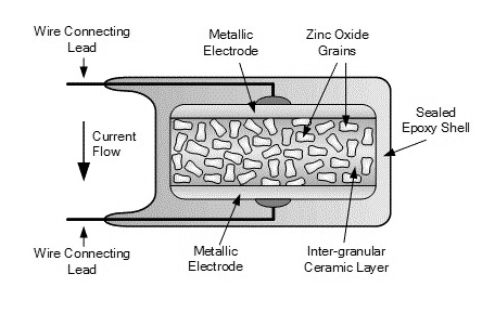
The metal oxide varistor (MOV) is composed of zinc oxide as an insulating material (ZnO). This zinc oxide was crushed onto a ceramic pallet. Only around 10% of the filler material used for proper connection formation is zinc oxide, with the remaining 90% being zinc oxide.
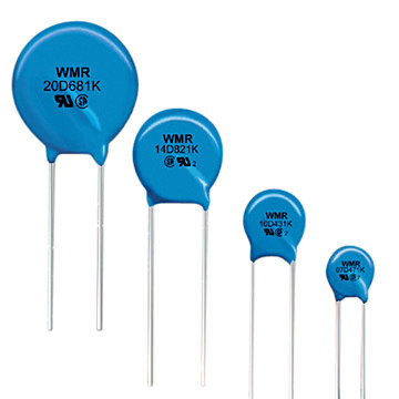
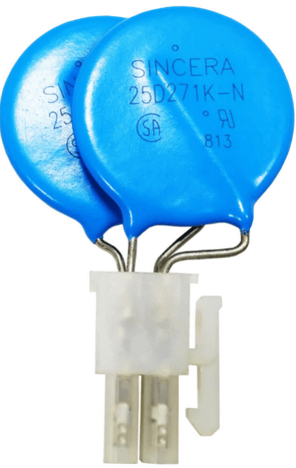
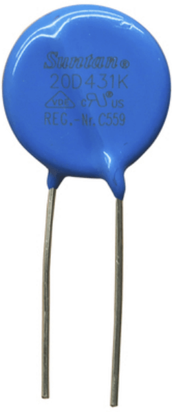
It is constructed with two leads and a durable epoxy outer casing. It resembles a disc capacitor in appearance. The rest of the building specifics are included below. It’s crucial to remember that a varistor must be carefully chosen from many options before being used. The most important criterion is the voltage, which should be 15 to 20% higher than the operational voltage.
How do Varistors Work?
The Varistor has a response time of ns, faster than a gas discharge tube but slower than a TVS tube. Overvoltage protection for electronic circuits can generally meet the requirements in terms of response speed. A varistor’s junction capacitance is often in the thousands of Pf range.
It should not be used to safeguard high-frequency signal lines directly in many circumstances. The huge junction capacitance will increase leakage when used to protect AC circuits. When designing a protective course, the current must be taken into account fully. A varistor has a higher flow capacity than a gas discharge tube, but it is smaller.
The current flowing through the Varistor is exceedingly small when the voltage applied to it is less than its threshold, which is akin to a resistor with infinite resistance. It is equivalent to an off-state switch when the voltage supplied falls below its threshold.
When the voltage applied to the Varistor crosses its threshold, the current flowing through it rapidly increases, resulting in an indefinitely small resistance. In other words, it is comparable to a closed state switch when the voltage applied to it exceeds its threshold.
The Resistance of a Varistor
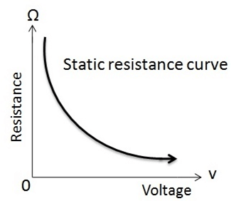
The resistance graph can be used to show how a varistor works. It’s a graph that shows the relationship between the resistor’s resistance and the applied voltage. The resistance is very strong in normal settings, as shown in the diagram. However, if the applied voltage exceeds the resistor’s rated value, the resistance will begin to drop.
The V-I Characteristics
We can see from the V-I characteristics graph that even a slight change in the applied voltage can significantly change the amount of current in the circuit. We can observe from the V-I characteristics graph that the Varistor behaves as if two Zener diodes were linked back to back. 1mA is the voltage at which the current begins to flow.
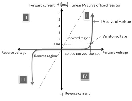
The Varistor transforms from an insulator to a conductor in this stage. This happens when the applied voltage is larger than the device’s rated voltage. This causes the semiconductor material to undergo the Avalanche effect, converting the Varistor from an insulator to a conductor.
Main parameters of the Varistor
Nominal voltage, voltage ratio, maximum control voltage, residual voltage ratio, current capacity, leakage current, voltage temperature coefficient, current temperature coefficient, nonlinear voltage coefficient, insulation resistance, static capacitance, and so on are some of the Varistor’s main parameters.
- When a 1mA DC is fed through the Varistor, the nominal voltage is the voltage across the Varistor.
- The voltage ratio is the difference between the voltage generated when the Varistor current is one mA and the voltage generated when the Varistor current is 0.1 mA.
- The maximum limiting voltage is the voltage that the two ends of the Varistor can withstand at the same time.
- Residual voltage ratio: The voltage created across a varistor when the current flowing through it is a given value is referred to as the residual voltage ratio. The ratio of the residual voltage to the nominal voltage is known as the residual voltage ratio.
- Under specific conditions, the through-current capacity, also known as the through-flow capacity, is the maximum pulse (peak) current that may pass through a varistor (with a specified time interval and number of times standard inrush current is applied).
- The current flowing through the Varistor at the stated temperature and maximum DC voltage is called the leakage current and waiting for current.
- When the current through the Varistor remains constant, the voltage temperature coefficient refers to the rate of change of the nominal voltage of the Varistor within a specified temperature range (temperature 20 70 °C), that is, the relative change of both ends of the Varistor when the temperature changes one °C.
- Moreover, when the temperature across the Varistor remains constant and varies by 1 °C, the current flowing through the varistor changes relative to the temperature.
- The nonlinear voltage coefficient is the ratio of a varistor’s static resistance to its dynamic resistance under a certain applied voltage.
- The insulation resistance is the amount of resistance between the Varistor’s lead (pin) and the resistor body’s insulating surface.
- The intrinsic capacitance of the Varistor is referred to as static capacitance.
The function of varistors
The Varistor’s main job is to safeguard the circuit against transient voltages. The Varistor is equivalent to a switch due to the mechanism mentioned above. The current flowing through the switch surges only when the voltage exceeds its threshold. The impact on other circuits is minimal, limiting overvoltage effects on subsequent sensitive circuits. The Varistor’s protective function can be employed frequently or turned into a one-time protection device, comparable to a current fuse.
The Varistor’s protective feature has been widely employed. A varistor, for example, is used in the power circuit of a household color TV to complete the overvoltage protection function. The Varistor reflects its clamping features when the voltage surpasses a threshold value. The high voltage is pulled low, allowing the next circuit to operate within the safe voltage range.
The Varistor is mostly employed in circuits for transient overvoltage protection. Still, it also serves as a circuit element because of its volt-ampere characteristics, comparable to a semiconductor Zener’s. The Varistor, for example, is a type of DC high voltage small current-voltage stabilizing element with a steady voltage of thousands of volts or more than silicon Zeners cannot achieve. Varistor can be utilized as a voltage fluctuation detector, a DC level shifter Bit, a fluorescent starter, a voltage equalizer, etc.
Metal oxide varistor
The most common Varistor is a metal oxide varistor (MOV), which consists of a ceramic block between two metal sheets and comprises zinc oxide particles and a small number of other metal oxides or polymers. At the intersection of particles and neighboring oxides, a diode effect occurs. It is equivalent to many back-connected diodes due to the vast quantity of dirt particles.
At low voltage, there is only a modest reverse leakage current. When a diode is exposed to a high voltage, it reverses collapses owing to hot electrons and the tunneling action, resulting in a huge current flow. As a result, a varistor’s current-voltage characteristic curve is nonlinear, with high resistance at low voltage and low resistance at high voltage.
Metal oxide varistors are the most prevalent voltage clamping devices today, and they can handle a wide range of voltages and currents. MOVs are particularly effective at absorbing short-term voltage transients and have superior energy handling capabilities due to the utilization of metal oxides in their structure.
Metal oxide varistors, like ordinary varistors, start conducting at a specific voltage and stop when the voltage falls below the threshold value. The fundamental difference between a typical silicon carbide (SiC) varistor and a MOV type varistor is that the MOV’s leakage current through the zinc oxide material is relatively tiny under normal working conditions, and its clamping transient operating speed is substantially faster.
MOVs are similar to disc ceramic capacitors in that they have radial leads and a hard outer blue or black epoxy covering, and they may be physically installed on circuit boards and PCBs in the same way.
To choose the right MOV for a given application, you must first determine the source impedance and the transient’s possible pulse power. Because the power supply characteristics are often unknown, selecting the suitable MOV for input line or phase transients is slightly more complex. In general, the electrical protection of MOV selection circuit power transients and spikes are based on the best guess.
On the other hand, metal oxide varistors can be utilized for a wide range of varistor voltages, from around 10 volts to more than 1000 volts AC or DC; thus, knowing the source voltage can assist you in picking. Choose MOV or silicon varistor as an example. The square voltage rating should be slightly higher because the maximum continuous voltage root is greater than the expected power supply voltage. A 120-volt power source, for example, is 130 volts RMS, while 230 volts is 260 volts RMS.
The transient pulse width and the number of pulse repeats determine the maximum surge current value the Varistor will employ. The transient pulse’s width, typically 20 to 50 microseconds (s), can be estimated. The Varistor may overheat and be damaged if its peak pulse current rating is insufficient. As a result, assuming the Varistor performs without fail or degradation, it must be able to dissipate the transitory pulse’s absorbed energy quickly and safely revert to its pre-pulse condition.
Main Applications of Varistors
Lightning Protection
Lightning strikes can cause atmospheric overvoltages, and inductive overvoltage is the most common type. Direct lightning overvoltage is caused by a lightning strike on a transmission line, and its voltage is exceptionally high, capable of causing significant damage at voltages of 102104V. As a result, steps to prevent overvoltage must be adopted for outdoor power systems and electrical equipment. ZnO varistor arresters are extremely good at removing atmospheric overvoltage. Electrical equipment is usually linked in parallel with it.
Multilevel protection can be employed if the electrical equipment demands a low residual voltage. Several popular safety circuits that use ZnO arresters to eliminate ambient overvoltage are listed below.
Switch Protection
When an inductive load circuit is abruptly severed, the overvoltage can be several times the power supply voltage. Overvoltage can produce arcing and spark discharge between contacts, causing damage to contactors, relays, and electromagnetic clutches and reducing the device’s service life. Because the Varistor shunts at high voltages, it can be utilized to protect the contacts by avoiding spark discharges at contact break.
The varistor protection switch or contact connection method is illustrated in the diagram below. The dry voltage of the switch and the dry voltage of the Varistor, when connected in parallel with the inductor, equals the sum of the Varistor’s residual voltage. The inductor stores the energy that the Varistor absorbs. When the Varistor is linked in parallel with the switch, the switch’s overvoltage equals the Varistor’s residual voltage. The energy absorbed by the Varistor is slightly greater than that stored in the inductor.
Device Protection
Varistors are frequently used to protect semiconductor devices from being burned due to overvoltage generated for various reasons. The varistor protection transistor’s application circuit is shown in the diagram below. Overvoltage damage to the transistor can be efficiently inhibited between the transistor’s collector and emitter or the transformer’s primary shunt varistor.
The Varistor has a high impedance and little leakage current at normal voltage. The Varistor quickly switches to a low impedance state when exposed to an overvoltage, and the Varistor absorbs the overvoltage energy as a discharge current. The Varistor returns to a high impedance condition when the surge voltage passes, and the circuit or component is exposed to a normal voltage.
How to test Varistors?
Preparation Before Varistor Measurement
To measure the real resistance value, connect the two test leads (regardless of positive or negative) to the two ends of the resistor. The range is chosen based on the nominal value of the measured resistance to increase measurement accuracy. The middle region of the ohm scale is fine due to the nonlinear relationship of the scale.
As a result, the pointer value should be as close as feasible to the scale’s middle, that is, within the range of 20% to 80% of the full scale’s radian. Between the reading and the nominal resistance, an error of 5%, 10%, or 20% is allowed, depending on the resistance error level. The resistor’s expected value is altered when the error range is exceeded.
How to measure the quality of a varistor?
A power source with a wide regulating voltage range and good current limiting action is usually required to judge the Varistor. A voltmeter with good precision is connected parallel across the Varistor when measuring. Connect both ends of the Varistor with the adjustable power lead.
The voltmeter displays the voltage of the power supply. You should gradually increase the voltage until you reach a point when the voltage drops dramatically. The protection value of the Varistor is the voltage at the last time before the reduction.
The resistance value of the Varistor can fluctuate from M (Megohm) to m (Megohm) when a constant voltage is applied to it (Milliohm). When the voltage is low, the Varistor operates in the leakage current region, with a large resistance and a small leakage current; when the voltage rises into the nonlinear region, the recent changes over a wide range, but the voltage does not change much, indicating a good voltage limiting characteristic; when the voltage is raised again, the Varistor operates in the saturation region, with small linear resistance and a small leakage current. Due to the enormous current, the Varistor will overheat, burn, or possibly burst over time.
Selection of Varistor
The specific conditions of the circuit must be examined while selecting a varistor, and the following criteria should be followed in general:
Selection of varistor voltage V1mA
According to the power supply voltage selection, the power supply voltage constantly applied across the Varistor must not exceed the “maximum continuous operating voltage” value indicated in the specification. The Varistor’s maximum DC operating voltage must be greater than the power line’s (signal line’s) DC operating voltage VIN, i.e., VDC VIN.
The power grid’s operational voltage fluctuation range must be thoroughly addressed when selecting a 220V AC power source. The domestic electricity grid’s general fluctuation range is 25 percent. Select a varistor with a varistor voltage ranging from 470V to 620V. Selecting a varistor with a greater voltage lowers the failure rate and extends the service life, increasing the residual voltage slightly.
Selection of Traffic
The Varistor’s nominal discharge current should be greater than the surge current necessary to sustain or the highest surge current during operation. The little discharge current may be computed by pressing the value of more than ten shocks in the rating curve of times of the surging life, which is around 30% of the maximum shock flux (i.e., 0.3IP).
Selection of clamping voltage
The clamping voltage of the Varistor must be lower than the maximum voltage (i.e., safe voltage) that the component or equipment under protection can withstand.
The choice of capacitor Cp
The capacitance Cp should be reduced for high-frequency transmission signals and vice versa.
Internal resistance matching (Resistance Match)
The following is the relationship between the internal resistance R (R2) of the protected component (line) and the transient internal resistance Rv of the Varistor: R5Rv; for the covered component with low internal resistance, you should try to use a large capacitor varistor without affecting the signal transmission rate.
Frequently Asked Questions
What is a varistor used for?
Circuits with varistors are protected from severe voltage spikes. When a circuit is subjected to a big voltage surge, the outcome is virtually always devastating. Across the signal lines, a capacitor could be put.
What happens when a varistor fails?
The current will increase when the Varistor heats up because it has a negative temperature coefficient. Thermal runaway may occur, resulting in varistor failure.
How do you test for Varistor?
One meter probe should be placed on the free varistor lead, while the other should be placed on the connected varistor lead. On the meter, read the resistance. The Varistor is still good if it reads virtually infinite resistance. The Varistor is blown if it reads very low resistance.
Do varistors have polarity?
Metal Oxide Varistors have two leads and are similar to resistors. These leads have no polarity and can thus be connected in any direction.
Why would a varistor burn out?
When the leakage current in a varistor is too high, and the temperature rises to a particular degree, the low melting point metal melts, causing the Varistor to fail.
Conclusion
In most electronic circuits, currents and voltages of milliamperes and millivolts are encountered. The input impedance of electronic circuits is quite high, and they are extremely sensitive. Overcurrent and overvoltage safety measures aren’t appropriate in this situation. A device that is both rapid and sensitive is required.
A varistor is a device that suits our needs and successfully controls voltage spikes, protecting our circuit. The name comes from the term “variable resistor.” Varistors are also used to preserve power electronic devices that handle huge currents.
Lastly, for more details or purchasing of vasistor or other electrical components, contact us at ICRFQ. We manufacture the best electrical components in China.
If you want to find more Electronic Components Distributors, please check out the following articles:
Electronic Components Distributors In the USA
Electronic Components Distributors In UK
Electronic Components Distributors In China
Electronic Components Distributors In India
Electronic Components Distributors In Singapore
Electronic Components Distributors In Malaysia
Electronic Components Distributors In Vietnam
Electronic Components Distributors In South Korea
- Where to buy IC chips? The Best Guide? - March 26, 2024
- Breaking Down Barriers: Overcoming Obstacles in Cross-Border Electronic Component Trade - March 4, 2024
- Everything You Need to Know About Amplifier IC Chips - March 4, 2024


