
Last Updated on October 22, 2023 by Kevin Chen
You might already know that in order to distribute electricity to different parts of a house or an apartment, you’ll need a separate transformer. This is because different outlets require different voltages.
The same applies to the smallest circuit in your product. The load distribution must be done correctly to take care of the voltage requirements of the different loads.
People often ask: “Why do I need to know about the voltage division rule?” This is an important concept in electrical theory.
Even if you don’t plan on becoming an electrician, having an understanding of the voltage division rule can help you save money. In this article, you will learn everything you need to know about the voltage division rule.
What is the voltage division rule?
The voltage division rule states that the total voltage applied across a system is divided by the number of resistors connected in series. This means that any voltage applied across a resistor is divided by the total number of resistors.
The rule simply means that the voltage drop is directly proportional to the total resistance across the circuit. The drop will be at its peak when the resistance is at the maximum level.
Voltage division rule simplified form
This means that if you add up all the voltages applied across each resistor, and then divide it by the total number of resistors, you will get the total input voltage.
Similarly, if you subtract all the voltages from the input voltage, and then divide it by the total number of resistors, you will get the output voltage. So this works both ways. The same thing applies to the current division rule.
The output current is equal to the sum of all currents flowing through each resistor divided by the total number of resistors as well as some of all currents flowing through each resistor minus the sum of all currents flowing through each resistor divided by the total number of resistors.
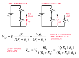
Voltage division rule formula
The voltage across each resistor is the same as the input voltage. The output voltage is equal to the input voltage divided by the total number of resistors in series. This formula is depicted as below:
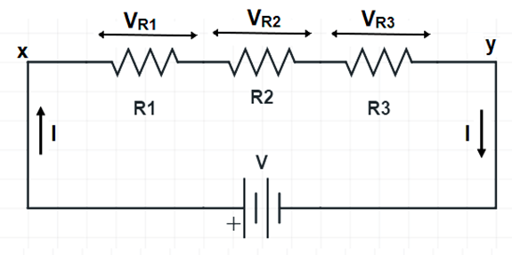
Let’s assume a circuit has three resistors, R1, R2, and R3. There is an input voltage of 12 volts and the total number of resistors is 3. The output voltage is equal to the input voltage divided by the total number of resistors in series.
Now let’s find out the voltage drop at each resistor. These will be Vr1 Vr2 and Vr3.
From our definition of the voltage division rule,
VR1, VR2, and VR2 should be directly proportional to the R1 R2, and R3.
We can write this as Vr1=KR1, Vr2=KR2 and Vr3=KR3. Keep in mind that K is constant.
However, the total voltage across the terminal of resistors connected in series is equal to the sum of the voltage drop across each terminal. We will calculate this using the formula;
V(total voltage)= Vr1+Vr2+Vr3.
K(constant)= V/R1+R2+R3
Now to the voltage distribution across each resistor, we can calculate it using the formula below;
V1r1=V/[R1/(R1+R2+R3)]
Vr2=V/[R2/(R1+R2+R3)]
Vr3=V/[R3/(R1+R2+R3)]
The voltage distribution in a circuit can be described as a ratio of voltage drops across resistors. Hence we can say that if the total number of resistors is N, then the output voltage will be V=Vr1/N+Vr2/N+Vr3/N.
In a series circuit, the total current is equal to the sum of currents flowing through each resistor. The total resistance is equal to the sum of individual resistances in a series circuit.
What is a voltage divider?
From the voltage division rule, we can have a voltage divider circuit. This is a simple circuit, where the output voltage is a fraction of the input voltage.
This type of circuit is also known as a potential divider or resistive divider. In this circuit, the input voltage is divided among several output voltages. This means that each output is at a fraction of the input voltage. Hence, in order to know the output voltage for each resistor, we must know the input voltage and the ratio of resistances in series with it.
The simplest form of a potential divider uses two resistors to provide two equal-voltage outputs from an unequal-voltage source.
In short, a voltage divider scales down the voltage in a circuit to a smaller value depending on the resistors.
The divider is usually used to supply power from a battery to a power source. Keep in mind that the output voltage is proportional to the resistance of the load in the circuit.
Ohms’s law in relation to voltage division
From the equations that we have analyzed, it is clear that there is a close relationship between Ohm’s law and the voltage division rule.
First Ohm’s law states that the voltage across a resistance is equal to the current through that resistance times its resistance value.
Secondly, the voltage divider rule states that the output voltage is proportional to the ratio of resistances in series with it.
Therefore, if we know the output voltage and the input voltage, we can easily determine the current flowing through a resistor in a circuit by using Ohm’s law.
Resistive voltage divider
Another method of understanding the voltage divider circuit is by analyzing the resistive voltage division.
This method is used to analyze the circuit in the following manner:
For a circuit with a resistor, if the voltage of the source is divided by 2, then the current is halved. If the voltage of the source is divided by 4, then the current is doubled.
If the voltage of the source is divided by 16, then the current value becomes 8 times that for which it was halved. So if we divide 1 V into 16 parts and connect them to a resistor in series, we get 1/16 V. Similarly if we divide 1 V into 32 parts and connect them to a resistor in series, we obtain 1/32 V.
Capacitive voltage divider
The concept of voltage division goes beyond the resistors. It also applies to capacitors.
As the name suggests, this rule describes the voltage drop across the capacitors connected in series and the circuit is from a single supply.
In most applications, capacitive voltage dividers are also used for stepping down the voltage from the power supply.
The circuit is designed in such a way that the current through the capacitor passes through a variable resistor. The value of the variable resistor is chosen such that it can be adjusted so that the voltage divider can be used to control the current.
In this way, we have created a voltage divider circuit with capacitors.
For a capacitor to perform its duty of dividing the input voltage, it must store energy. This stored energy is released when the capacitor is charged and vice versa. The charge stored on a capacitor depends on its capacity, dielectric constant, and leakage current.
Capacitive voltage dividers are mainly used in modern communication devices such as smartphones and tablets.
Inductive voltage dividers
The voltage division rule also applies in the inductance voltage dividers. As the name suggests, The voltage division here applies to the inductive coils connected to a common power circuit.
An inductive coil is a coil of wire (usually a coil of wire wound around a ferromagnetic core) in which the magnetic flux through the coil is changed as a result of a change in current.
The change in magnetic flux, induced by such a change in current, results in an electromotive force, or voltage, across the coil. When the current changes direction, so does the voltage.
Applications of voltage division rule
The voltage division concept is used in the manufacturing and running of different devices. Some of the application areas include;
Potentiometer
A potentiometer is a variable resistor – an electrical component that adjusts the current in a circuit as a function of the position of a knob or lever. It is used to adjust or vary the amount of resistance in an electrical circuit, often as a control input for other components. The device utilizes the voltage division rule in that, when the knob is rotated, the voltage across the resistor changes. This change in voltage causes a corresponding change in current through the circuit connected to it.
Transformer
A transformer is a device that transfers electrical energy from one circuit to another. Transformers are widely used in power supplies, audio amplifiers, motors, and other applications. The primary function of a transformer is to increase or decrease an alternating current (AC) voltage by creating an equivalent direct current (DC) voltage by dividing it into two separate circuits.
The voltage division is also used in AC motors which run on an AC power supply and convert that into DC power for running the motor.
Rotary angle sensor (grove)
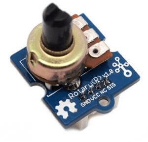
The rotary angle sensor (also called a rotary switch or rotary potentiometer) is a type of potentiometer. It is used to detect the rotation of a shaft or wheel in an electric motor, the position of which can be measured by an encoder.
A rotary angle sensor is used in turning on and off switches, as well as gauges, valves, and other mechanisms.
Conclusion
I hope the article has given you valuable insights into what the voltage division rule is and its application. I am sure you will be able to apply it in your future projects.
And if you need any electronic components that will utilize this rule, don’t hesitate to contact us. We as ICRFQ will help you source the right electronic components in China.
If you want to find more Electronic Components Distributors, please check out the following articles:
Electronic Components Distributors In the USA
Electronic Components Distributors In UK
Electronic Components Distributors In China
Electronic Components Distributors In India
Electronic Components Distributors In Singapore
Electronic Components Distributors In Malaysia
Electronic Components Distributors In Vietnam
Electronic Components Distributors In South Korea
- Where to buy IC chips? The Best Guide? - March 26, 2024
- Breaking Down Barriers: Overcoming Obstacles in Cross-Border Electronic Component Trade - March 4, 2024
- Everything You Need to Know About Amplifier IC Chips - March 4, 2024


