Last Updated on October 22, 2023 by Kevin Chen
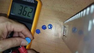
Image source Electronics Hacks
Varistors play an important role in electric circuits. They protect the circuit from voltage surges and other unexpected events that may occur on the electric circuits. As long as you are interested in matters pertaining to electricity, you should know how to test varistors. This knowledge will come in handy in many different situations.
One such situation is when you are troubleshooting the electric circuit to solve a particular problem. Another scenario is when you have just bought the varistor and want to be sure it is in perfect working condition.
Keep reading as we outline clear steps on how to test a varistor. Other than the steps, we will also recommend safety tips that you should consider when doing the tests.
Why should I test a varistor?
Like most electronic components, varistors are not 100% perfect at all times. There are times when they degrade in terms of performance. A new varistor may also have one or more manufacturer’s defects. With the safety role that a varistor plays in an electric circuit, it is important to test it.
Here are the top reasons why you should test a varistor.
- To be sure of the circuit’s security: As we have mentioned, the primary function of a varistor is to protect the circuit from voltage surges. By testing it, you will have an assurance that your circuit is completely safe. In other words, testing eliminates the chances of having a false sense of security.
- To be sure of the operation and functioning: Just like any other type of testing, you will do so on a varistor to be sure that it is in perfect operational condition or shape. You will never know that the varistor works if you don’t test it.
- To diagnose the circuit: This is another common reason why you should consider testing a varistor. A problem in the circuit can be due to faulty electronic components. Varistors may be among the faulty components that need to be worked on or even replaced.
- To be in line with the laws and regulations: You may test the varistors just to comply with the regulations of your jurisdiction. This can be your organization or even the local area.
Testing varistors using a multimeter
The main method of testing a varistor is by using a multimeter. Here, you will have to find out the internal resistance of the varistor and it will tell you whether the device is functional or not.
You will need the following tools and equipment to do the tests:
- Multimeter
- Solder
- A datasheet
- Flux
Why do I need a soldering iron? Well, it may come in handy when you will want to disconnect the varistor from the circuit. While it is possible to do the measurements without having to remove the varistor, our goal is to improve the accuracy of the testing process.
A datasheet is product documentation from the manufacturer. It will give you all the details and specifications of the device on which the varistor was on. You will also know the expected resistance of the varistor.
During the measurement, you should cross-check the value on the varistor and that of that on the datasheet. The value should not be more than or less than 10% of what is on the sheet.
Step 1: Disconnect the varistor from the power
Like when undertaking any other electronic procedure, you should start by disconnecting the varistor from the power source. This is a key safety measure to protect you from electric shock.
You will do this by simply turning off the power. After that, you can unplug the device from the power outlet or socket.
Do not start working on the device immediately after the power is off. Instead, give it a few minutes (20 minutes). This period will give the device time to lose its leaked current and electric charges hence will be safe to work on.
Step 2: Disconnect the varistor from the circuit
In most cases, varistors are embedded into circuit boards. As we have already mentioned, you can only get accurate values if you separate it from the rest of the circuit.
You will use the soldering iron to safely disconnect the varistor from the rest of the circuit board. Ensure that you know how to use this tool as any mistake can damage the whole circuit board. And this applies to all other soldering tools that you can use. You can also use wire clippers and cutters if you are sure of your skills.
Take note of the position and configuration of the varistor on the circuit before disconnecting it. This will ensure that you have an easier time when putting back after testing.
Step 3: Setting the multimeter
Now that you have a varistor ready, it is time to focus on the multimeter. Since we will be testing the internal resistance of the varistor, you will have to set the multimeter to the resistance mode.
Do you know how to use a digital multimeter? You can select different settings by rotating the switch which will allow you test different modes, whether it is electric current, voltage or resistance. You will also be able to see the units of measurements. Since our focus is on the resistance, the units will be in ohms (Ω).
For most digital multimeters, you will have to select the range of resistance. The range will always depend on the expected resistance value as defined on the datasheet. For example, it can range between 10Ω to 100Ω.
Step 4: Get the measurement on the multimeter
In this step, you will get the resistance value of the varistor. To do this, simply touch the two probes of the multimeter to the leads of the varistor. I guess you are aware that the probes are color-coded to match with the polarity of the leads. The red is for the positive terminal while the black probe is for the negative terminal.
Avoid using any other conductor to touch the probes to the varistor leads. Doing this may compromise the accuracy of the results as the conductors may have their own internal resistance.
Step 5 Observe and analyze the multimeter readings
Now is time to take note of the readings on the multimeter after making the connections as we have stated in the previous steps.
Start by checking the reading when no voltage has been applied on the varistor. It is expected that you should get the highest resistance. A low resistance reading on the multimeter is a sign that the varistor could be having a serious issue that needs to be rectified.
Otherwise, you should be comfortable when the reading is significantly high. However, it should fall within the actual resistance value as per the manufacturer’s datasheet.
Step 6: Apply some voltage to the varistor
In the previous step, we tested the resistance of the varistor when not connected to any circuit. This time round we will apply some voltage. Create a simple circuit of 5 volts and let the varistor be part of it. A small battery should be enough to give you the 5V that you will need for testing.
Remember to keep the multimeter connected to the varistor
Step 7: Take note of the reading
Observer the multimeter reading even after applying some voltage to the varistor. The most obvious observation that you should make is a significant drop in the value of resistor. However, if the resistance reading on the multimeter remains high, there could be a problem with your varistor.
If possible, you can try to increase the voltage to the varistor while observing the reading. The resistance should be coming down with every increase of the supply voltage.
Visually inspect the varistor
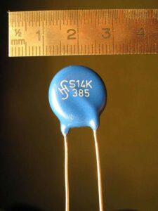
Image source wikipedia
Other than the above steps, you can inspect the varistor to determine its state. Check out for any signs of physical damage such as cracks and corrosion. Keep in mind that a damaged varistor will not function perfectly as expected.
If you spot any signs of damage, then you should proceed to buy a new varistor for your application.
Can I use a fluke multimeter to test the varistor?
Yes, you can proceed to use a fluke multimeter if you do not have a digital multimeter as we have described above. To do this, start by ensuring that the multimeter is in resistance mode. From there you can connect its probes on the terminals of the varistor.
The resistance reading on the multimeter should remain constant regardless of the voltage. If it changes, then it is a sign of damaged varistor. You may need to do further diagnosis to identify the problem.
Conclusion
Now you know everything that entails testing a varistor. By using the right tools and following the steps that we have discussed here, you should be able to the tests successfully. While at it, remember to follow all the necessary safety precautions about electricity. For example, wear safety gear and carry out the procedure in a well-lit room. If not sure, consider contacting professional electricians for help.
If you want to find more Electronic Components Distributors, please check out the following articles:
Electronic Components Distributors In the USA
Electronic Components Distributors In UK
Electronic Components Distributors In China
Electronic Components Distributors In India
Electronic Components Distributors In Singapore
Electronic Components Distributors In Malaysia
Electronic Components Distributors In Vietnam
Electronic Components Distributors In South Korea
- The Ultimate Guide to IRFZ44N MOSFET - April 30, 2024
- AMD Ryzen 5 vs Intel i5: How to Choose the Right Processor? - April 30, 2024
- Where to buy IC chips? The Best Guide? - March 26, 2024