Last Updated on October 22, 2023 by Kevin Chen

Image of voltage level shifter circuit source MakerPro
Voltage level shifting is quite a common term in the world of digital electronics. Voltage level shifters are also known as level converters, voltage level translators, or logic level shifters. These are electronic circuits that are used for translating electric signals from one logic level to another. The translation can also be from one voltage domain to another. The translation is necessary because in most applications, different integrated circuits are required to work together to achieve a common goal. However, these ICs have different voltage requirements; some have high voltage while others are low. A voltage level translator will be required to make these ICs compatible with each other.
In most electronic applications, logic shifters are used for bridging domains between processors and sensors. The most common voltage logic levels include 1.8V, 3.3V and 5V. However, the voltage may be higher or lower than the mentioned values depending on the application areas.
How are voltage logic level shifters made? Different electronic components are combined to serve the purpose of logic level shifting. Transistors tend to be one of the components that are used for making voltage level shifters. In this article, we are going to discuss in detail how to make level shifters using transistors.
Overview of transistors as voltage level shifters
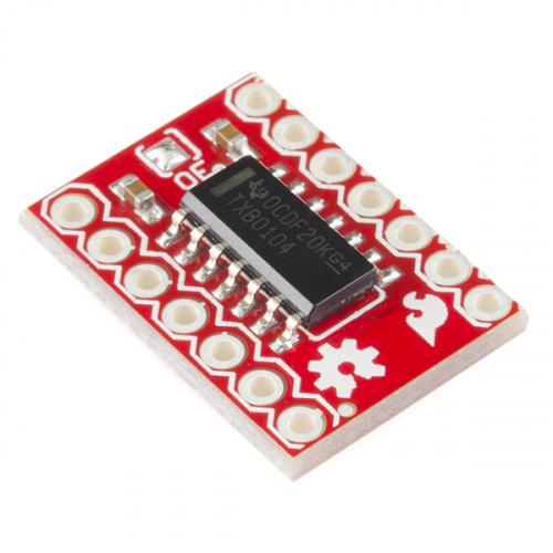
Image source Sparkfun
Transistors are widely used in the logic level shifting. This is mainly due to their function to function as switches and as well as amplifiers. With the transistors, the outgoing signals will definitely be different from that of the incoming signal. Let’s take an example of the amplification. The output signal will be of a higher level than the input signal. The same principle works when the transistor is used as a switch. The output signal will be different from the incoming signal. It can be on or off depending on the application needs.
When it comes to the transistor for level shifting, both the two major types of transistors are used for making these shifters. We have MOSFET level shifters and as well as well as BJT level shifters. What matters is how you configure the transistor.
Also, when building a level shifter using a transistor, you will have to consider the current and voltage requirements of the circuit. Coupled with other electronic components, you will be able to achieve the desired level of voltage shifting.
Steps of building voltage level shifter using transistors
How do I use a transistor to build a voltage level shifter? Here are the steps that you should follow to build one. You can do this in your local lab or garage.
Step 1: Circuit design
The very first step of the process entails designing an appropriate electric circuit for the project. The transistor should be among the components that will make up this circuit and, in our case, we will use an N-channel MOSFET transistor. You will also need a resistor for the purpose of biasing and regulating the flow of electric current through the transistor. To make it easier, you should go for a 2N2222 transistor. This one is classified as an NPN bipolar junction transistor and is used for amplification purposes in low-power applications.
The circuit design should also consider the flow of signals in electric circuits. For the purpose of voltage level shifting, we are considering the bi-directional shift which means that the movement of signals will be in two directions. Each voltage domain of the circuit has both the input and output pins and the direction of the signal can change. This means that once the external signal has changed, the output can be the input, and the input be the output.
Testing the circuit
The second important step is proof of concept. You have to ensure that every part and as well as the component of the circuit works perfectly as expected. To do this, you have to implement the circuit design from the previous step into an actual circuit. A breadboard will be a perfect platform on which we can implement the actual transistor voltage level shifter.
To build this circuit, place your 2N2222 BJT transistor on the breadboard while taking note of its terminals, the collector, the emitter, and the base. To make the job easier, mark these terminals using the letters E, B, and C.
How do I connect the transistor terminals? The base terminal (B) should be connected to a resistor and its other end to the voltage source. You should connect the emitter terminal (E) to the ground. The collector terminal is connected to the output signal of the circuit. The input signal is connected to a resistor R1 and is rated at 5V.
Test the output signals for each input voltage. Whenever the input voltage is 1.8V, the output should be 3.3V. If the input voltage is 0V, the output should also be 0V.
Step 3: Build a circuit board
After confirming that the circuit on the breadboard is functional, you can now build an actual transistor voltage shifter on a printed circuit board (PCB). There are different tools that you can use for designing a printed circuit board. With the tool, you will know the exact placement and positioning of each electronic component.
After designing the board, you can proceed to build a prototype of a transistor voltage level shifter. Be careful when handling each component and placing on the PCB to prevent causing any physical damage.
Step 4: One last test
Now that you have implemented the voltage level shifter on the PCB, it is time to do another round of testing. To do this, you will have to connect the circuit to a NodeMCU board as it is designed to provide direct access to the input and output signals of the circuit. Find out the behavior of the output signal with every input voltage that gets into the circuit. Make all the necessary corrections in case the values do not match until you are fully satisfied with the setup.
Check out the video below for detailed information on how to use transistors for level shifting.
If you want to find more Electronic Components Distributors, please check out the following articles:
Electronic Components Distributors In the USA
Electronic Components Distributors In UK
Electronic Components Distributors In China
Electronic Components Distributors In India
Electronic Components Distributors In Singapore
Electronic Components Distributors In Malaysia
Electronic Components Distributors In Vietnam
Electronic Components Distributors In South Korea
- The Ultimate Guide to IRFZ44N MOSFET - April 30, 2024
- AMD Ryzen 5 vs Intel i5: How to Choose the Right Processor? - April 30, 2024
- Where to buy IC chips? The Best Guide? - March 26, 2024