Last Updated on October 22, 2023 by Kevin Chen
We all know what a resistor does in an electric circuit. It is a component responsible for limiting or resisting the flow of electric current. There are various situations when you don’t want current to flow in a particular direction or through a specific section of a circuit. A resistor will come in handy.
Resistors come in different sizes, shapes, designs, and types. They are usually represented by different symbols to make things easier both for technical and non-technical people.
The most common symbol for a resistor is a zigzag line which serves as a representation of a resistor element. The zigzag is positioned horizontally to the circuit and has two leads attached at each end. The leads represent the terminals of the resistor elements.
Why are resistor symbols important?
A typical electronic circuit diagram should have symbols that represent various electronic components. In our case, the symbol is a resistor and it shows that the circuit has a resistor placed at a particular position on the circuit. Without a symbol, you will have a difficult time understanding the basics of the circuit and what it does.
Electric engineers and technicians fully rely on the resistor symbols to understand the electric circuit when working. From the symbols, they will know the type of resistor and its value. They can then come up with appropriate designs and necessary solutions for the circuits.
For example, they will need the electronic components symbols when troubleshooting the electronic circuits. From the symbols, they will know the exact location of the resistors in the circuit and narrow down their solutions within that location. They will also be able to execute proper adjustments and their troubleshooting efforts will be much easier.
So, overall, the resistor symbols are vital for electronic circuit analysis and design. They improve the simplicity and accuracy of working on the circuits.
Resistor color code
Other than the basic symbol, you should also be cognizant of the fact that resistors come in different color codes. These codes represent the value of resistance. A typical resistor code comprises colored bands that are painted on the surface of the resistor. Each code stands for a specific resistance value.
Still, on the resistor code system, the 4-band code is considered the most common code and each color band represents a particular attribute of the resistor. These include resistance value, temperature coefficient, and tolerance among others. You should read these color bands starting from left to right.
Types of resistors
Before we even get deep into the resistor symbols, let’s have a look at the different types of resistors.
- Carbon film resistors: These resistors have been around for many years and the resistive elements comprise of carbon and a binding agent.
- Metal film resistors: The presence of metallic material in these resistors increases their high coefficient temperature. They are stable and have high accuracy levels. Also, tend to have a high power rating.
- Oxide film resistors: This type of resistor offers reliable resistance to heat and pressure. They are usually considered the perfect substitute for metal film resistors.
- Surface mount resistors: As the name suggests, they are directly mounted on the surface of the circuit board.
Fixed vs variable resistors
The other two major classes of resistors that you should know when it comes to resistor symbols are fixed resistors and variable resistors.
The fixed resistors are designed to have a specific value of resistance. All the above types of resistors that we have outlined are fixed resistors. The specific value of resistance is indicated on the surface of the resistor. You simply need to check the color code or watch out for the numerical value as indicated by the manufacturer.
On the other hand, variable resistors allow users to adjust the value of resistance. These resistors comprise a resistive element as well as a movable wiper which you can move around to change the resistance value. Variable resistors are quite common in applications where a change in resistance will effect changes in the output such as the brightness of light and audio.
Despite these different types of resistors, all of them are represented by the same symbol: a zigzag line. However, there are different ways in which the resistors are represented in the circuit diagrams. This is done to give clarity on the type of resistor that has been used.
Resistor marking symbols
In most cases, the resistor markings are represented by different letter symbols such as R RN, RF, and FS. A fixed resistor is represented by the letter R while a potentiometer is represented by RP.
Also, a couple of Latin letters are used to indicate the type of resistor used. In an electric circuit diagram, you will see letters such as RT whereby the R stands for resistor while the T represents the conducting material being used. The third letter is added to represent the expected performance of the resistor.
For example, you will see the letters RJJ being used on a resistor symbol. The R will be for the resistor, ‘J’ for the metal film, and the last ‘J’ will indicate the precision of the resistor( how accurate it is)
The symbol for a fixed resistor
There are two symbols that re commonly used to denote a fixed resistor. A zigzag line and a square. And these symbols are used on all types of fixed resistors (carbon film, metal film, and others)
The symbol used will always vary from one geographical location to another. The figure below shows the symbols of fixed resistors.
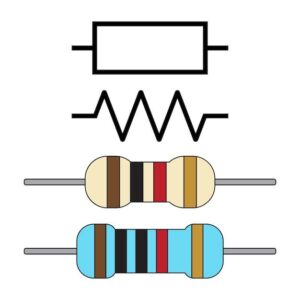
Image source Freepik
Symbol for a variable resistor
The symbols for variable resistors are slightly similar to those of fixed resistors only that there is an extra arrow to represent the movable slider. So, it can be a long square or a zigzag line then an arrow. Of course there are two terminals at the ends of each symbol to represent the lead wires.

Image source Freepik
Preset resistor
This type of resistor is right in the middle of the fixed and adjustable resistor. Although you can adjust the resistance value, the adjustment should be within a defined range. It is usually used on circuits that do not require frequent changes of the resistance value. Here is the symbol of a preset resistor.
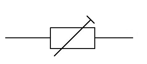
Image source Freepik
Symbol of a potentiometer
A potentiometer is a type of adjustable resistor that allows users to adjust the value of resistance using a knob or sliding a slider. RP are the textual symbols used to represent potentiometers in a circuit diagram. Otherwise, the actual symbol comprises of a broken line and an arrow.

Image source Wikipedia
Symbol of a fuse resistor
A fuse resistor works as a normal resistor only that it has extra features that makes it play the protective role in a circuit. Under normal circumstances, the resistor will operate as an ordinary resistor. But once the current exceeds a certain limit, the fuse element of this resistor will melt to break the current.
Fuse resistors have different colors. In some applications, they are black while in others they are represented by a green color. A fuse resistor is usually represented by various letters such as F, FB, and L. The surface of these resistors is marked with their specific values.
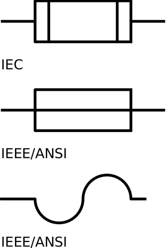
Fusible resistor image symbols.com
Thermistor symbol
A thermistor is a type of resistor designed to change its resistive value depending on the external temperatures. They are usually used in temperature-sensitive applications. The symbol for a thermistor resistor is similar to that of a fixed resistor (a zigzag or a long square). However, it may have extra markings to show that it is temperature sensitive. For example, the letter “TT may be added next to the zigzag line or in a long square.
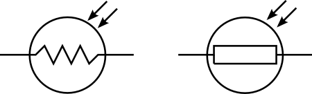
Image source All about circuits
Photoresistor
This is a light-controlled resistor-its resistance value will depend on the intensity of light that hits the resistive elements. So, you should expect the symbol to have some light-like objects. Check out the photoresistor image below.
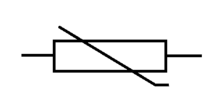
Image source starting electronics
In some symbols, the circle casing is there and it is missing in other symbols. But one constant element is the arrows depicting the light source. Letters such as “RL” and “RG” are usually put next to the symbols. Some photoresistor symbols have two pins while others have three pins.
Symbol of varistor
A varistor is a type of variable resistor whose resistance value depends on the applied voltage. It is also known as Voltage-dependent Resistor (VDR) and is non-linear and non-ohmic.
Initially, the symbol of a varistor was represented by two diodes parallel to each other. This stems from the fact that this resistor has features of a diode. Otherwise, these below are the standard symbols of varistors.

Image source Wikipedia
Symbol of humidity-sensitive resistor/humistor
This type of resistor is affected by the humidity of the external environment. “RS” is the letter used to symbolize the resistor. Check out the symbol below
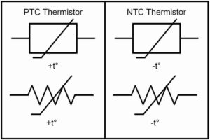
Image source Apongeeweb
Conclusion
Now you know the different symbols of resistors and what they mean. So, next time you are working on a circuit diagram, everything should be clear with regard to the symbols used. When it comes down to buying resistors in China, ensure you get from the right suppliers.
If you want to find more Electronic Components Distributors, please check out the following articles:
Electronic Components Distributors In the USA
Electronic Components Distributors In UK
Electronic Components Distributors In China
Electronic Components Distributors In India
Electronic Components Distributors In Singapore
Electronic Components Distributors In Malaysia
Electronic Components Distributors In Vietnam
Electronic Components Distributors In South Korea
- The Ultimate Guide to IRFZ44N MOSFET - April 30, 2024
- AMD Ryzen 5 vs Intel i5: How to Choose the Right Processor? - April 30, 2024
- Where to buy IC chips? The Best Guide? - March 26, 2024