22-23-2021
Part Number: 22-23-2021
Manufacturer: Molex
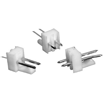
Description: Rectangular Connectors
Shipped from: Shenzhen/HK Warehouse
Stock Available: Check with us
ICRFQ.com - Electronic Components Distributor in China Since 2003

We make your sourcing easier!
Get A Fast Quote Worldwide!

Part Number: 22-23-2021
Manufacturer: Molex
Description: Rectangular Connectors
Shipped from: Shenzhen/HK Warehouse
Stock Available: Check with us
Because the device we will discuss today is a through-hole connector, I figured it would be beneficial for us first to understand what a through-hole technology is before delving further into the device that is the subject of this discussion.
Through-hole technology (or “thru-hole” technology) is a method of attaching electronic components in which the components’ leads are soldered to pads on the opposite side of a printed circuit board (PCB). Manual labor or automated insertion mount equipment can accomplish this task. One alternative name for through-hole technology is “thru-hole” technology.
In almost all cases, earlier methods of assembling electronic components, such as point-to-point construction, were rendered obsolete by through-hole technology. Between the time of the second generation of computers in the 1950s and the time that surface-mount technology (SMT) started to gain popularity in the middle of the 1980s, every component on a standard printed circuit board (PCB) was a through-hole component.
In the beginning, tracks were only printed on one side of a PCB. Later, both sides were printed on, and eventually, multi-layer boards were used. For the components to make contact with the necessary conductive layers, the through holes were converted into plated-through holes, abbreviated PTH for short. Plated-through holes are not required for making component connections when using SMT boards. However, plated-through holes are still utilized for making interconnections between the layers. Plated-through holes that serve this function are more commonly referred to as vias.
Compared to SMT techniques, through-hole mounting is known to provide stronger mechanical bonds; however, the boards produced using this method are more expensive due to the additional drilling required. On multilayer boards, the holes also restrict the available routing space for signal traces on layers immediately beneath the top layer since they must pass through all the layers to reach the other side of the board. As a result, through-hole mounting techniques are now typically reserved for heavier or larger components.
Regarding prototyping, design engineers frequently prefer larger through-hole components over surface mount components. This is because larger through-hole components can be easily used with breadboard sockets. SMT technology may be necessary to reduce stray inductance and capacitance in wire leads, both of which have the potential to impair a circuit’s functionality in designs that operate at high speeds or frequencies. Even in the prototype design phase, ultra-compact designs might require surface mount technology (SMT) construction.
Through-hole components are the most convenient when prototyping circuits with breadboards and microprocessors like Arduino or PICAXE. Because of their size, these components can be easily soldered by hand.
Components with wire leads are typically used on circuit boards with through-holes. On the geometrical axis of symmetry, axial leads project outward from each end of an element that is generally cylindrical or box-shaped and extends in an elongated fashion. Axial-leaded components have a shape similar to that of wire jumpers. They can be used to bridge relatively short distances on a board or even unsupported distances through open spaces in point-to-point wiring. A low-profile or flat configuration is produced by axial components when placed “lying down” or parallel to the board. This is because axial components do not protrude much above the surface of a board. Radial leads emanate more or less in parallel from the same surface or aspect of a component package instead of from opposite ends of the box.
At one point, the definition of radial leads meant that they were to more or less follow the radius of a cylindrical component (such as a ceramic disk capacitor). In contrast to axial leads, this definition evolved to take on its present-day form and became more general over time. Radial components “stand up” perpendicular when placed on a board. These parts are functional in a wide variety of high-density systems thanks to their compact profile, which takes up less of the valuable “board real estate” available in some cases.
Due to their parallel leads that extend out from a single mounting surface, radial components can be employed in high-speed automated component insertion machines. The result is that everything feels more “plug” than ever before. Converting an axial component into a radial one is as simple as bending one of the leads into a “U” shape so that it ends up near to and parallel to the other lead. This can be done to fulfill the demands of the current work.
To prevent a short from occurring between neighboring components, you could add additional insulation using heat-shrink tubing. A radial component can be transformed into an axial part by disconnecting its leads and extending them over the entire length.
Even though these improvisations are common in breadboard or prototype construction, they are not recommended for designs intended for mass production. This is because it is difficult to use with automated component placement machinery and has a lower level of reliability since the finished assembly has a lower level of resistance to vibration and mechanical shock.
Diodes, integrated circuits (ICs), transistors, and resistor packs, all of which have many leads, can be mounted directly into a PCB or plugged into a socket using standardized semiconductor packages.
Like the 256R devices, this CMOS A/D converter uses a differential potentiometric ladder for 8 bits of resolution. This converter is designed to be utilized with the NSC800 and INS8080A derivative control bus, and its TRI-STATE output latches will be responsible for powering the data bus. No special interface logic is required because the microprocessor will see this A/D as just another set of memory locations or I/O ports.
For +180°C polarization, the system employs offset header entry holes that permit power and signal to travel through the same casing. This connector system can be loaded with polarization keys and pegs to prevent accidental remitting of headers and housings.
It is used in Communications & Networking, Automotive, Medical, and Consumer Electronics
We hope you like it. If you have any questions, feel free to submit them in the comment sections below, and we will do our best to respond to each one.
If you need to order 22-23-2021 or any other electronic component, ICRFQ is the place to do it. In China, we have become the market leader for electronic components. Contact us today, Place your order immediately to ensure you receive the best item at the lowest possible cost.
WhatsApp us