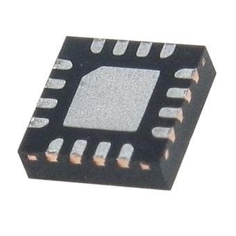
EP53F8QI
Part Number: EP53F8QI
Manufacturer: Intel / Altera
Description: Switching Voltage Regulators SYN PWM DC-DC CONV 1500mA.
Shipped from: Shenzhen/HK Warehouse
Stock Available: Check with us
ICRFQ.com - Electronic Components Distributor in China Since 2003

Part Number: EP53F8QI
Manufacturer: Intel / Altera
Description: Switching Voltage Regulators SYN PWM DC-DC CONV 1500mA.
Shipped from: Shenzhen/HK Warehouse
Stock Available: Check with us
| Datasheet | |
|---|---|
| Category | Power Supplies – Board Mount |
| Family | DC DC Converters |
| Manufacturer | Altera |
| Series | 5300 |
| Packaging | Tape & Reel (TR) |
| Part Status | Active |
| Type | Non-Isolated PoL Module |
| Number of Outputs | 1 |
| Voltage – Input (Min) | 2.4V |
| Voltage – Input (Max) | 5.5V |
| Voltage – Output 1 | 0.6 ~ 4.96 V |
| Voltage – Output 2 | – |
| Voltage – Output 3 | – |
| Current – Output (Max) | 1.5A |
| Power (Watts) – Manufacture Series | – |
| Voltage – Isolation | – |
| Applications | ITE (Commercial) |
| Features | Remote On/Off, OCP, OTP, SCP, UVLO |
| Mounting Type | Surface Mount |
| Package / Case | 16-QFN |
| Size / Dimension | 0.12″ L x 0.12″ W x 0.04″ H (3.0mm x 3.0mm x 1.1mm) |
| Operating Temperature | -40°C ~ 85°C |
| Efficiency | 94% |
| Power (Watts) – Max | – |
Are you sick of power systems that are cumbersome and hard to understand? If you’re looking for a comprehensive power system on silicon, go no further than the EP53F8QI, a breakthrough DC-DC converter device. With its built-in magnets, this full module is intended to provide extensive engineering evaluation options, such as the flexibility to add more input and output capacitors for testing a wider range of setups.
The board has pre-placed resistors and a jumper to select one of four predetermined output voltages, making it easy to program the output voltage using a resistor divider. This product is made for the user’s convenience, with features like quick-connect jumpers for enabling and VOUT, many test locations, and clip leads for making input and output connections. In addition, the EP53F8QI safeguards against typical installation errors through features like input decoupling and input reverse polarity protection. The EP53F8QI is a great way to modernize your electrical setup now.
Several features set the EP53F8QI apart from conventional power systems. With four preset output voltages accessible on the evaluation board, programming the device’s output voltage with a resistor divider is simple. Input and output connections are made via clip leads and multiple test pins, which makes the board easy to use and troubleshoot.
The EP53F8QI is ideal for individuals seeking to experiment with various input/output capacitor combinations. The device can accommodate additional input and output capacitors, enabling performance testing over a wide variety of configurations. A pre-tinned pad is provided for an additional 0805 case-size MLCC capacitor. The board is pre-populated with the input capacitance need of 10 uF and 680pF MLCC capacitor parallel. The minimum output capacitance needed is 22uF, and there is room on the pre-tinned pad for up to one more output capacitor with an 0805-case size.
The EP53F8QI has test point connections that reduce the voltage drop across the line and load cables, which can result in misleading readings to assure reliable measurements. Series ammeters or precise shunt resistors can be used to monitor input and output current, which is crucial when assessing efficiency.
The EP53F8QI, a ground-breaking DCDC converter product, provides engineers with a full power system on silicon, integrated magnetics, and various features that make assessment and experimentation easier. The EP53F8QI can help you upgrade your power system right now.
A straightforward resistor divider is used to configure the EP53F8QI’s output voltage. The evaluation board already has a set of four jumpers that the user can use to select one of four preset voltages. The default voltage value is 0.6V if no jumper is occupied.
Any desired output that falls within the device’s operational range can also be produced by removing one of the preset resistors and substituting one with a different value. Further information on adjusting the output voltage can be found in the product data-sheet.
The required input capacitance is a 10 uF and a 680pF MLCC capacitor connected in parallel. The EP53F8QI must be positioned next to the 680pF capacitor, which has a lower value. To reduce the physical size of the input AC current loop, both capacitors have been positioned as near as feasible to the device.
For experimenting with the performance of the input filter, there is a pre-tinned pad that accepts an additional MLCC capacitor with the 0805-case size. A minimum of 22uF must be present in the output capacitance. A single 22uF 0805 case size MLCC capacitor is the only component on the evaluation board. A pre-tinned pad on the board can accommodate up to one additional output capacitor with an 0805 case size.
Overall, the EP53F8QI is a cutting-edge DC-DC converter that boasts a thorough power system on silicon, integrated magnetics, and several practical features to ease experimentation and evaluation. The EP53F8QI is a crucial tool for anyone looking to upgrade their power system because of its readily configurable output voltage, test points, and clip leads and the opportunity to add additional input and output capacitors for performance evaluation. The product also includes input decoupling and reverse polarity protection to safeguard the device from frequent setup errors. Upgrade your power system with the EP53F8QI today to take advantage of this revolutionary component. For reliable and high-quality components, ICRFQ is the trusted supplier to purchase from, providing exceptional customer service and excellent products to ensure top-notch results.
WhatsApp us